 Previous section
 Return to TactileView manual overview
In this section you can find a first introduction to some of the first software functions you will come across when you create a tactile design.
After launching the software, the red border is showing the current paper size and orientation.
The word ‘Title’ can be found in the top left corner. This is to make you aware of the importance of a title in your design, which will help the reader to understand the content of the diagram at hand.
When you open a new design, you will see a tactile marker in the upper right corner. This so-called right-up marker helps a blind reader to easily find out the paper orientation without having to explore its contents first. This the position of the right-up marker is always in the top right corner, independent of landscape or portrait orientation. On screen, the marker is shown as three blue lines at an angle of 45 degrees.
For most designs we advise you to include the right-up marker for ease of use. However, by clicking on the marker it can be turned off, which for example can be used if you want to print multiple designs in a bundle and bind them. A red marker will remain which can be activated to switch the marker on again.
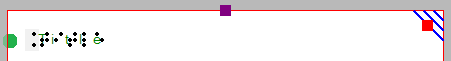
Figure 1. The top of the design shows the title text label, right-up marker and red border for paper size and orientation.
Design orientation: landscape or portrait designs
Choosing the right paper orientation for your design allows you to make optimal use of the available space on the paper. This way the image can be presented as large as possible in order to retain smaller details. You can change the paper orientation by clicking on the ‘Change the orientation to landscape/portrait’ icon in the design toolbar (second vertical toolbar when nothing is selected). You can also find this option in the Design menu.
It is important to know that changing the paper orientation will not adjust the size of the image! This ensures that the tactile quality of the image is maintained. However, you might need to adjust the width and/or height manually to fit the new paper orientation by dragging the markers around the design.
‘Change the orientation to portrait’ icon: ![]()
Portrait to landscape orientation
When you start with a design with a tree in portrait mode and you decide you want to have it in landscape, you can change the paper orientation. The size of the white design area that contains the tree will stay the same.
It is likely that the lower part of your design will now be outside the red border and that you have two sheets of paper instead of one. Even though you could have a design spread over multiple sheets, chances are you would want to reduce the design size to fit a single sheet of paper. You can use the blue marker in the lower right corner to make the height of the tree fit. Please note that your tree has become smaller, so make sure any smaller details are still adequate for tactile use. Next, use the purple marker in the middle of the right side of your design to add paper to span the width of the paper.
Landscape to portrait orientation
The other way around, you might start with a tree that spans the height of a design in landscape orientation, but decide you want it to be in portrait to make better use of the length of the paper. In that case, you could increase the size of the image by using the blue marker in the lower right corner. You can use the purple markers in the middle of the two sides of the white area to trim any empty space left and right of the tree.
For more information, see section ‘Paper size vs. design size‘.
Line view and Dot view
To get you familiar as soon as possible with the effect of creating designs for braille embossers, you can view the design on screen as it will be embossed in dots.
For good visibility you can use the line view mode for the drawing. When you switch to dot view, all lines will be converted to individual dots, just as your braille embosser will do.
You can read more in the section ‘Design mode: dot view/line view‘.
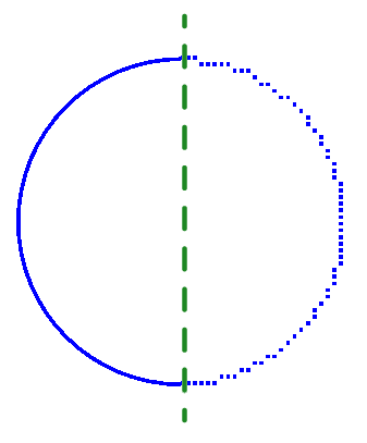
Figure 2. A circle shown in line view (left) or dot view (right) shows the graphic capabilities of the selected embosser.