Ikkunassa on seuraavat toiminnot.
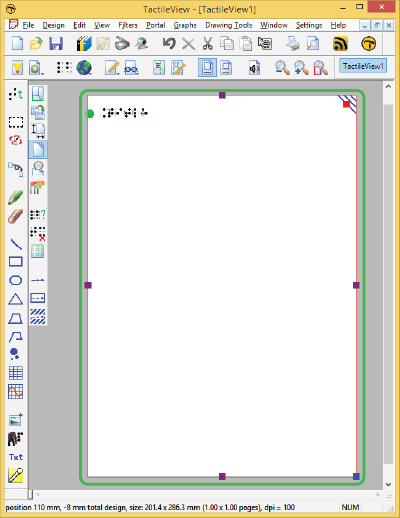
In the centre of the TactileView window you can find the drawing area of the design. The drawing area is surrounded with a red border, indicating the size of the printable area on the selected paper size for the selected printer. Some printers have larger margins along the edges of the paper that cannot be printed, resulting in a smaller area within the red border compared to other printers.
The white area shows the actual size of the contents of your design. The size of the contents can be increased in size both horizontally and vertically to span multiple pages. If the white area does not fit within the red border of the printable area, you can reduce the size to make it fit within the page(s) using the purple markers on the four sides. The blue marker in the lower right corner is used to scale the entire design.
All software functions are situated around this drawing area.

Figure 1. Drawing area highlighted in green.
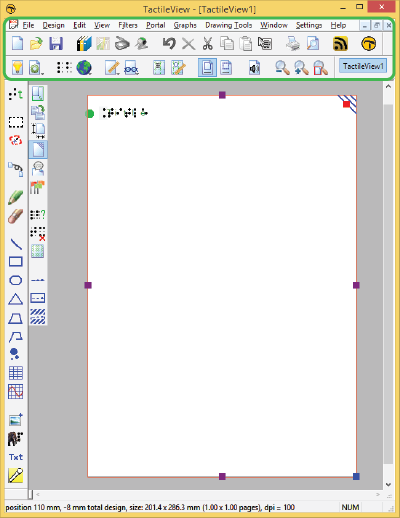
Above the drawing area, you can find three elements: the software menus, two horizontal icon bars and the names of the opened documents. The top row of icons are general functions for the software, whereas the second row contains functions related to the design that you are working on in the drawing area. In some icons, a small arrow indicates that there is a dropdown toolbar with additional options. Most icons will depict the function that they represent. To get more information, your can hover over the icon with the mouse. Tooltips in your selected language will be displayed, explaining which function will be activated when you click on the icon.

Figure 2. Menus, horizontal icon bars and file names.
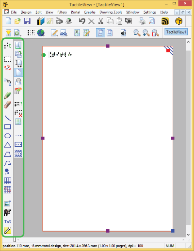
On the left hand side you can find two vertical icon bars. The leftmost vertical icon bar contains all the drawing tools to create graphics or modify the content of your design. By selecting one of these tools and clicking in the drawing area, different objects can be placed.
The right vertical icon bar will show the range of properties for the current selection. This can either be the drawing tool selected from the left toolbar, or the object in the design that has the focus. You can (re)select an object by clicking on it in the design area.
Once again, tooltips will explain which functions are represented by the icons in the vertical toolbars.

Figure 3. Vertical icon bars give access to the drawing tools and the options for the selected tool or element in the design.
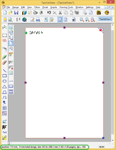
Below the drawing area you will find the status line, showing mouse position, dimensions, etc. for the selected drawing tool or object in the design.

Figure 4. Status bar near the bottom of the software window gives information about the selected element or drawing tool.

 Return to TactileView manual overview