The triangle with the two 45 degree and one 90 degree corners is referred to as to the 45triangle. The rectangular 45triangle has the same measurement indication as the drawing board. The two short sides have a range of 10 centimetres, while the long side has a length of 14 centimetres. There are four holes in the triangle for fixing it over the knobs of the drawing board.
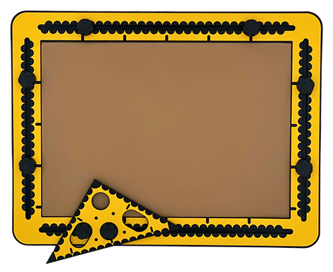
Photo: The 45 triangle aligned with a side of the frame.
At a distance of one centimetre from the right corner a hole is made. In the middle of the long side, one centimetre distance to the edge, a hole is made. To the left and right are two long holes. Along the short sides small indents per centimetre are present. The long side (hypotenuse) is slik. Small grooves in the top surface indicate distances of five centimetres. Pushpin markers are available.
Basically all tools that have a straight side can be used as a ruler. It is a matter of preference and which tool is most handy. The slik side of the 45triangle is sometimes preferable because tracing the pen tip along an indented side causes hold ups.
Using the knobs in the drawing board frame
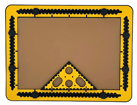
The round hole in the 90 degree corner fits around a knob. Aligning one of the short sides of the triangle with the edge of the frame, makes two angles on the board, one of 90 and one of 45 degrees.
When putting the hole in the middle of the long side and one of the others over a knob, an angle of 30 or 60 degrees can be made by turning the triangle to its extreme position.
Photo: The hole in the middle of the long side on a knob and one of the oblong holes on a second one. The 45triangle is rotated.
Bar chart example; 10 centimetres stands for 100%
Place the drawing board in landscape orientation. Place one of the knobs in both vertical grooves 16 centimetres from the top. Add the ruler on to the knobs. The edge is now at position 15. Draw a line.
Align the 45triangle
Find the five centimetres position of the ruler. Align the short side of the triangle with the ruler so the 45 degrees corner is pointing to the right. Draw a line along the vertical side of the triangle. Start at position 10 and draw the line downwards, on to the ruler. 10 Centimetres represent 100%. While the tool is still in place, mark positions 2,5, 5 and 7,5 with the pen. Move the triangle two centimetres to the right (position 7) and draw a line starting at five which represents a value of 50%. Create more bars where one centimetre stands for 10%. Horizontally there is enough space to create bars for the 12 months of the year. With a spacing of two centimetres you can add a character or a mark below the bar to indicate a specific bar.
Please note: Bar charts generally have two lines that make up for one bar. Here the bar is only one line wide. The space between the bars is there to distinguish one from the other.
The triangle with 30, 60 and 90 degrees corners is referred to as to the 30triangle. When the three corners of the triangle are set 30, 60 and 90 degrees respectively, it is known as a ‘1/2/sqr(3) triangle’. As a given, the three sides always have these proportional lengths. For practical reasons, the longest right side (sqr(3)) of the triangle tool is set to 15 centimetres (about 6 inches). The length for the other two sides can then be calculated as 15/sqr(3) multiplied by 0.5 or 1 respectively. (8.66 and 17.3 centimetres). The 30 degrees corner is pointing to the left when the surface with the tactile measurement indications is facing up and the 90 degree angle is at the bottom right.
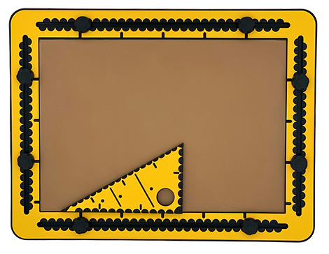
Photo: The 30triangle with the 30 degrees corner pointing to the left.
For the two sides connecting at the 90 degree corner, the measurement indications are in centimetres. The distance between the units along the hypotenuse is somewhat arbitrary! For the 30triangle it was decided on 20 units spread over 17.32 centimetres, which is rounded 0.87 centimetre per unit. With this regular pattern it is easy to count/measure from both the 30 and 60 degrees corners onwards in groups of 5 units. The measurement indications at the top surface of the triangle are semi circles. At each measurement unit also a small indent is provided. Per five units a short groove at the top surface is provided for easy counting.
As a tactile guidance, when following the two long narrow grooves in the top surface, they are pointing to equal positions on the longest right side and the hypotenuse. A hole of two centimetres can be found near the 90 degree corner. It can be used to place the triangle over one of the black knobs in the TactiPad frame. Pushpin markers are available.
Considerations for the design
In the design story you can read about the practical approaches that where taken to determine the measurement system for the hypotenuse. The insights may help to utilise the tool.
The hole near the right corner can be placed around one of the knobs. Aligning one side of the 30triangle with the side of the frame offers a 60 or 90 degrees angle in reference to the paper edge.
3D coordinate system
Put the drawing board in landscape orientation. Draw a vertical line at 10 centimetres and a horizontal one at 15 centimetres. Align the triangle with the ruler where the 30 degrees corner is at the crossing of the two lines. Draw a line along the hypotenuse. In a 3D coordinate system the hypotenuse is the X axis. The longest side aligned with the horizontal line serves as the Y axis. The vertical line is the Z axis. You can decide if you want to use any measuring system along the axes.
Draw a cube with sides eight centimetres; exercise
Note: In this exercise no coordinate system is used.
Maybe having a die is handy to imagine the below. In total 12 lines are required to form the cube. The eight corners are named A, B, C and D for the bottom surface and E, F, G and H for the top surface. The corner E is positioned above corner A. The line A-B is horizontal and going to be nearest to you. For the length of the sides eight measurement units are taken; centimetres or the small ones along the hypotenuse. The order in which the lines are drawn may seem illogical, but moving the tools around is minimised.
Steps to take:
Step 1: Place the ruler at 15 centimetres horizontally in order to make sure the lowest side of the front face is horizontal in reference to the paper’s edge.
Step 2, rib A-E: Find the position five along the ruler. Place the 30triangle against the ruler with its right corner pointing to the right here. Draw a line along the triangle’s short side downwards from the eight position on to the ruler.
Step 3, rib A-D: Shift the triangle to the right until the 30 degrees corner is at the A corner. Hold the triangle tight against the ruler. Draw a dashed line spanning eight units along the hypotenuse. Make sure there is at least a line fraction at corners A and D.
Step 4, rib A-B: Draw along the ruler for eight centimetres from the corner A, the point where the rib A-E touches the ruler.
Step 5, rib B-F: Move the triangle’s right corner to the right over eight centimetres to the end of the line A-B. Draw the line from the eight position downwards on to the ruler.
Step 6, rib B-C: Move and align the triangle further to the right until the 30 degrees corner is at corner B. Draw for this rib a solid line with the length of eight units along the hypotenuse.
Step 7, rib C-D: Move the ruler up as far as the line endings of the lines A-D and B-C just peep out from underneath the ruler. Find corner D, draw a dashed line to the right to corner C. This completes the bottom face of the cube. (A-B-C-D)
Step 8, rib D-H: The ruler is already in a good position. Place the triangle with the right corner at corner D and draw a dashed line along the triangle from the eight position downwards on to the ruler.
Step 9, rib C-G: Move the triangle to the right until the right corner of the triangle is at corner C. Draw a solid line from the eight position downwards on to the ruler. At this stage only the top face has to be finished.
Step 10, rib E-F: Move the ruler up until the end points of the lines A-E and B-F peep out from underneath the ruler. Create a line between the two endpoints of the vertical ribs. The front face is ready.
Step 11, rib E-H: The ruler is again in a good position. Place the 30 degrees corner at corner E while holding the triangle against the ruler. Draw a solid line with a length of eight units along the hypotenuse. Corner E and H do exist already.
Step 12, rib F-G: Move the triangle to the right, place the 30 degrees corner at the F corner. Draw a solid line along the hypotenuse with a length of eight units. The right hand face is completed.
Step 13, rib G-H: Move the ruler up and connect the two line endings at corners H (left) and G (right).
You are done!
Using a 3D coordinate system for a cube
Once a 3D coordinate system is created, few of the ribs are already available. There are two options to choose from: Corner A at the position where the three axes cross or corner D at this position. In case A is at the crossing, corner E is on the vertical (Z) axis. Otherwise you find corner H here. Drawing a cube can be perform with a square tool faster. See the manual section on the TactiForma square tool. The grid boxes provided by the GraphGrid enable indicating the corners of the cube. Or other 3D figures. The motorised drawing arm (MDA) is even faster. In addition It enables to draw the cube in any rotation angle over the X, Y or Z axis.
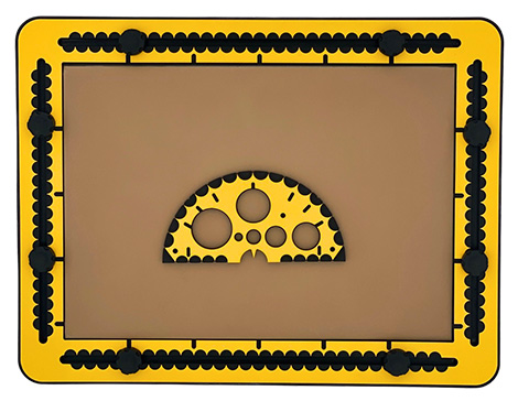
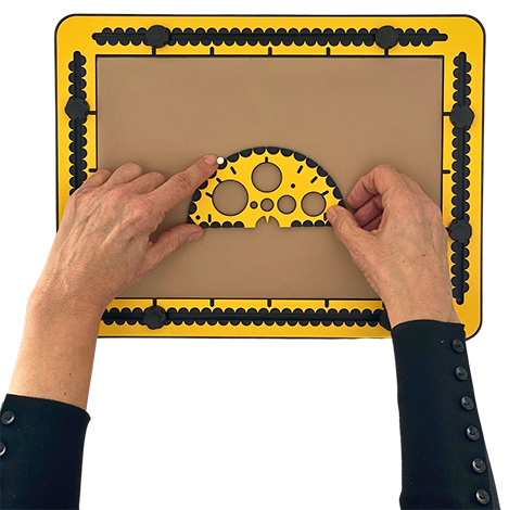
The shape of the protractor makes up for a half circle with a radius of 7 centimetres. In the middle of the straight side a 2 centimeter wide semi-circular hole Is located. In here an arrow head points down to the centre of the circle. Six differently sized circles are provided scattered around the top surface that serve as templates.
Along the bottom side of the protractor, which is the diameter line of the circle, centimetre indications can be found at the top surface. Along the edge small indents are located. The straight side is interrupted half way, where the arrow head can be found. As a note, purposely, the arrow head does not fully reach out to the line that is made up by the bottom line of the protractor. At the top surface, following te round side, semi-circles indicate steps of 10 degrees. The edge has also small indents. Small grooves at the top surface indicate the usual 30, 45, 60 and 90 degrees angles. The round holes have a diameter of 0.5, 1, 1.5, 2, 2.5 and 3 centimetres respectively. Pushpin markers are available.
Along the top side the semi-circles indicate steps of 10 degrees. They are wide enough to discriminate with a fingertip the ‘bottom’ of the semi-circle, which is per five degrees. Splitting up this space even further, enables rather precise determining the amount of degrees.
Creating a corner
Draw a horizontal line at 10 centimetres. Mark with the pen the position M of the corner. Align the bottom of the protractor with the line. Make sure the arrow had points to M. This point is accessible because it is not covered by the protractor. Determine the amount of degrees for the angle and mark with a pen or place a pushpin at the edge of the protractor at position P. Create a line between position M and the position P.
Photo: The protractor is on the drawing board. The thumb holds the bottom side. The pointing finger is measuring the 55 degrees corner. A pushpin is provided here.
Measuring a corner
To measure a corner align one half of the bottom of the protractor with one of the lines that make up the corner. Make sure the arrow head is pointing exactly to where the two lines of the corner cross. Reade the degree indication along the top surface and or the indents along the edge.
The six holes as templates for circles
Place the protractor on the drawing board and choose a circle. To ensure the pen tip remains as close as possible near the circle’s edge during tracing the contour, tilt the body of the pen towards the centre of the circle. Now follow the edge of the circle with the pen, until you are at the starting point again.
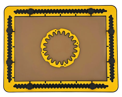
The wheels in the set have 12 and 20 teeth respectively. The body of the spur wheel is a circle with eight finger fitters around the outside. The body width is about six millimetres. From this inside circle the ‘negative’ teeth are pointing towards the centre. After tracing the inner contour, the spaces between the teeth are in fact the positive teeth around the outside of the spur wheel. Pushpin markers are located in the top surface of the body.
Remarks
There are different types of spur wheels for various applications. Although it looks like any number of teeth can be placed around a circle, this is not the case. The TactiForma spur wheels represent the mechanical properties with which the force from one wheel on to the other is maximised. When the two wheels are interlinked, their teeth always have a point of contact under an angle of 90 degrees while rotating. This gives an impression of how delicate spur wheel systems are in mechanics.
Even while the two spur wheels differ in diameter, the size and shape of the teeth on both wheels are similar. For practical reasons the largest spur wheel can hold the smaller one, this has nothing to do with the actual diameters of the wheels.
We recommend to use two pushpins to fixate to tool on the TactiPad, because a spur wheel is a relative time consuming shape to create. Place a spur wheel somewhere on the TactiPad and draw the inner contour. You have set the first step into the mechanical domain.
Interlinking the 12 and 20 teeth spur wheel
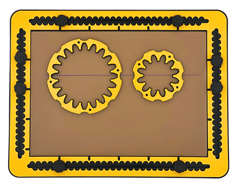
Once you have interlinked two spur wheels, you will experience a complex issue: finding the perfect position for one tooth on the one and one tooth on the other wheel to “bite each other”. The distance between the centre positions of the two spur wheels is 17 centimetres. Draw a straight line and align the spur wheels with the finger fitters with this line. Carefully check the positions of the teeth! You may need to slightly rotate the second spur wheel.
Photo: 2 spur wheels aligned with their finger fitters on a straight line,
Finding the centre position of the spur wheel
The open space at the inside of the spur wheel does not make it easy to place the centre on a pre-defined position. You have to create support lines and align the tool with the finger fitters. Let us know your experiences.
Fantasy: Spur wheel as the start for a flower
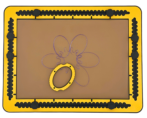
Use the 12 teeth spur wheel. Combine this with the 6*4 centimetres ellipse in the ‘horizontal’ or ‘vertical’ orientation.
Enclose three teeth within the ellipse and draw the whole or a part from the ellipse. Repeat this three times until you have got all teeth covered. Alternatively enclose two teeth within the ellipse and draw the shape five times for a more delicate flower. You can add more details with a equilateral triangle.
Photo: A flower made of the spur wheel and ellipse.
We use cookies to ensure that we give you the best experience on our website. If you continue to use this site we will assume that you are happy with it.Ok