A math teacher came to us with the question: ‘Can you create a 30/60/90 degree version of a triangle tool for the TactiPad?’ He wanted his students to draw 3D shapes such as cubes, prisms and pyramids. Being keen to improve and extend Thinkable product range we took up this challenge.
After describing the details of the tool, we present some of the decisions we made during the design process. You will also find information on some of the aspects of the representation of three-dimensional space using the TactiPad.
Contents
- The first section the physical and tactile product details.
- Section two describes our use of two different methods to decide on the units of measurement for the slanted side of the TactiPad triangle tool. The first of these methods includes a step-by-step description of how to draw a cube using the triangle tool and the TactiPad.
- Section three deals with the creation of a coordinate system on the TactiPad drawing board and explains why an angle of 30 degrees for the X axis is most efficient for drawing 3D shapes as tactile diagram.
- Section four gives some hints for best practice.
I Product specifications
Product name
Apart from the mathematical name of the shape, from now on, the term ‘triangle’ refers to Thinkable’s TactiPad Triangle Tool as well. We will also use the name ‘369Triangle’.
Dimensions of the 30/60/90 degrees TactiPad triangle tool
When the three corners of the triangle are set 30, 60 and 90 degrees respectively, it is known as a ‘1/2/sqr(3) triangle’. By defination, the three sides always have these proportional lengths. For practical reasons, the longest right side (sqr(3)) of the triangle tool is set to 15 centimetres (about 6 inches). The length of the other two sides can then be calculated as 15/sqr(3) multiplied by 0.5 or 1 respectively (8.66 and 17.3 centimetres).
The 30 degrees corner points to the left when the surface with the tactile measurement indications is facing up and the 90 degree angle is at the bottom right.
Measurement indication along the three sides
For the two sides connecting at the 90 degree corner, the measurement indications are in centimeters. The size of the units used on the slanted side is arbitrary since, unfortunately, there is no standard for this. For the TactiPad triangle we decided on 20 units spread over 17.32 centimetres, which is rounded 0.87 centimeter per unit. With this regular pattern it is easy to count/measure from both the 30 and 60 degrees corners onwards.
Tactile properties of the triangle
The measurement indications at the top surface of the triangle are semi-circles. At each measurement unit a slight indent is provided. When combining touching the semi circles and counting the tactile clicks that occur when tracing the pen along the sides with the indents, the speed of finding the correct position increases.
Every five units a short groove at the top surface is provided for easy counting. This is a standard provision in all TactiPad tools. As a tactile guide, when extending the two grooves in the top surface, they are pointing to equal values on the longest right side (referred to as the Y axis) and the slanted side (referred to as the X axis).
A hole of two centimetres can be found near the 90 degree corner. It can be used to place the triangle over one of the black knobs in the TactiPad frame.
II Determining the measurement indication for the slanted side of the triangle
Convention for the X, Y and Z axis setup
As we work in centimetres, the units for the Y and Z axis both have these distances corresponding with the measurement indication of the TactiPad.
The X axis is the slanted line that ‘comes out of the paper’. The Y axis is drawn as a horizontal line. The Z axis is the vertical line. The Y and Z axis are under an angle of 90 degrees. In theory the angle between the X axis and the Y axis can range from – let’s say – 25 to 45 degrees. The point where the three axes cross is called the origin (O). This is also the position to count units positive or negative from.
The size of the units used for the X axis is arbitrary, as this differs depending on different projections and there is no scientific consensus. For more information on the matter see Wikipedia. More importantly, the scale we use should serve as a good indication of tactile distance.
There are two variations of triangles with a 30, 60 and 90 degrees corner; one pointing left and the other pointing right. The one we selected for our triangle aligns with the coordinate system on the TactiPad.
Photo: The two variations of the triangle printed with 3D print technique
Two approaches to determine the units of measurement for the slanted side
In order to determine a suitable value for the units along the slanted side of the triangle we thought about two approaches: Drawing a cube and looking for a ‘nice’ practical distribution of units along the slanted side of the triangle.
Photo: Cube with sides 6*6*6 centimeters drawn on the TactiPad
First approach: drawing a cube
The cube has a dimension of 6 by 6 by 6 centimetres, Its vertices are labeled from A to H, with the first vertex being positioned at the origin point (0, 0, 0) and the cube itself being aligned with the axis system and existing entirely in the positives of all three dimensions. Its bottom surface is aligned with the X-Y plane, it’s back side being aligned with the Y-Z plane and one of it’s sides being aligned with the X-Z plane.
This projection has three pairs of similar surfaces: top and bottom, left and right, and the front and rear, with this last pair being visible as squares inside the projection.
The bottom surface has the corners A, B, C and D, with the A corner at the zero (0, 0, 0) position and the others going counter-clockwise from here.
We start from the zero position, and by moving 6 centimeters to the right along the Y axis to mark the position of the D vertex with the pen and a pushpin. The line from A to D is therefore the rear side of the bottom surface.
The front side of this same surface is in parallel to this, however in order to measure the exact distance between the two lines it is necessary to set up a measurement unit for the X axis.
As an experiment, and in order for the sides of this bottom surface to have a length of 6cm by virtue of the properties of the special right triangle (30/60/90 degree triangle), we draw a long support line 3 centimeters bellow the back line and parallelly to it. Using pushpins, we mark the intersection of this support line with the X axis as point B and a point 6 cm to the right as point C, with the segment between them becoming the front side of this surface.
By connecting point A with point B and point C with point D we fully trace the bottom surface.
At this point we are missing the 4 vertices that form the top surface, which are labeled from E to H, with the E point being 6 cm along the Z axis above the A point, and the other points once again being labeled counter-clockwise.
Point H is found 6cm along the Y axis from point E and therefore also 6 cm along the Z axis from point D. After marking points E and H we can now trace the rear side of the top surface by connecting both points. To finish tracing the full rear surface, which would not be visible from the front, we connect point A with point E and point D with point H.
We mark point G by drawing a vertical line connecting point C with the X axis and marking the intersection. As the X axis serves us as a guideline we can do this easily with our triangle tool. We repeat the same process starting from point B to mark the final vertex (F). By connecting the points F and G, the front face is complete, and by connecting point E with point F and point G with point H the cube itself is completed.
Testing with the 30/60/90 degrees triangle
Given the proportions of the sides of a special right triangle (30/60/90 degrees triangle) we know, that when the shortest right side is three centimetres, the slanted side has a length of six centimetres. This length is a result of the fixed proportions of the three sides and can be concluded from the photo below as well.
Photo: The 30/60/90 degrees triangle partly covered with the right side for a length of three centimeters. Along the slanted side another triangle is positioned to measure the distance from the 30 degrees angle to where the two triangles meet. The distance is six centimeters.
Considering this we evaluate whether this proportion results in sufficient tactile space and a cube with a good appearance. What do you think? In our opinion, the distance is just a little bit too big, and hence we would like to have a scale with units shorter than 1 centimetre for the X axis and the slanted side of the triangle, which we use to plot and measure it.
Units along the slanted side should measure less than one centimeter
So, when we conclude that the distance between the front and rear side of the bottom surface has to be shorter, the effect is the six units along the slanted side have to ‘shrink’. Imagine you move the right hand side triangle in the above photo to the left, thus towards the 30 degrees corner, this is clearly demonstrated.
Second approach: A practical number of units for the slanted side
Remember our starting point where we wanted to have a practical number for the amount of units. Grouping units per five would be helpful to be able to count fast starting at one of the two corners.
This would not be the case with any other number than 20 or 25. Dividing 17.32 by 20 gives us a distance of 0.87 centimetres between units. When multiplying this distance with six, we get the position for the B corner on the X axis of the cube. (6*0.87 equals 5.22 centimetres). Half of this is also the distance between the front and rear surfaces.
The calculation 17.3/25 * 6/2 gives the outcome 2.07 centimetres. This distance is to short; the front and rear surface are too close for a good tactile discrimination.
III. Aspects of the the creation of 3D space in detail
Two types of coordinate systems on the TactiPad drawing board
In order to draw a 3D shape you need a coordinate system first. There are two main approaches:
- Take a regular (2D) grid setup where grid boxes are squares; indicated by solid lines or by just dot markings at the crossings and then draw the three axes.
- Otherwise draw the three axes under their respective angles and provide the units of measurement along the axes.
Methods to create the coordinate system
There are a few techniques to create the coordinate system with the Thinkable products:
- The measurement indications along the four sides of the TactiPad in combination with the ruler act as reference for axes and grid boxes. You can draw the axes along the ruler.
- Alternatively the TactiPad GraphGrid with its rubber bands provides a ‘flexible’ grid. Additional rubber bands wrapped around the frame provide the axes.
- The preferred method which is faster and more flexible, is to have the motorised drawing arm (MDA) sketch the grid paper as a 2D or a 3D setup in your preferred measurement configuration.
Angle of the X axis in a 3D coordinate system
In a 3D coordinate system, the Y axis is usually drawn as a horizontal line and the Z axis as a vertical line, and hence, for both of these lines it is possible to use the lines of grid paper as guides. However there are many different approaches to drawing the remaining X axis. Mainly depending on the resulting aesthetic appearance of shapes plotted inside such a system and personal preferences:
- One of these approaches is to draw it diagonally on the grid, resulting in a 45 degree X axis. In practice however, this setup does not always result in an optimal angle to draw 3D shapes, with the axis itself being too steeply inclined.
- Two other common options are to use a different angle for the X axis: starting from a 2D grid you count two units to the right and one up or three to the right and two up to find each position where the X axis would intersect with the squares of the grid. The angle of the line looks much better. Unfortunately, the angles are not an exact round amount of degrees and are more difficult to (tactually) align with a drawing tool.
- When the axis is positioned at an angle of exactly 30 degrees, the grid line crossings cannot be used anymore as a reference. However, aligning lines with other parts of the drawing has become much easier, especially with a dedicated tool that has corners of 30, 60 and 90 degrees.
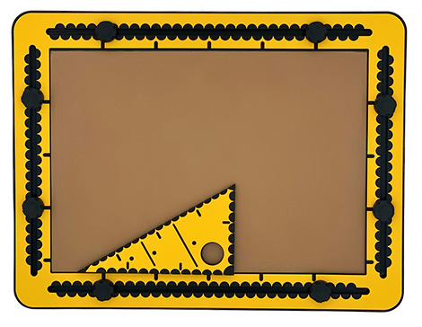
Photo: The 30/60/90 degrees triangle tool with the 30 degrees angle pointing left. Along the two right sides centimeter indications. And along the longest side: a tactile indicator per unit less than one centimeter.
IV. Using the triangle in a (prepared) coordinate system
Once the coordinate system is prepared on the TactiPad, with or without measurement units along the axes, you can start adding coordinates and add lines.
Motorised drawing arm (MDA)
With the interactive module ‘3D coordinate system’ you can create your 3D space. When including the measurement indications along the axes, they are in accordance with the triangle. Of course measurement units can be set/scaled to inches or other distances as well, given by any regular grid.
Counting and/or measuring
Finding distances on the axes or the triangle requires some exercising. Using push pins for marking positions is recommended. The triangle is easy to align with the axes or other existing lines in the drawing.