Congratulations on the TactiPad drawing board! We wish you an inspiring drawing experience.
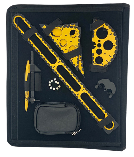
Of course you want to see as soon as possible the TactiPad and all its tools and parts that are stored in the carrying bag. When opening the bag you find all the parts at their own positions: TactiPad, ruler, compass, 30 triangle, 45 triangle, protractor, 10 pushpins, pen and 50 sheets of drawing foil.
Take the drawing board from its pocket and explore out all its properties. Take a sheet of drawing paper from the paper pocket and follow the instructions on how to place it on the drawing board. See the section for a description of the drawing board. Probably, you can’t wait to experience your first raised lines. Take the ballpoint pen from its elastic tube.
You are now fully ready to start using the tools and bring your creations to life. Read the general and detailed descriptions of the tools as well as the respective manuals for applications and exercises.
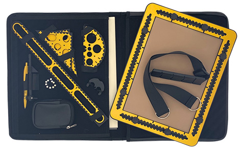
The TactiPad with all its tools and parts comes in a carrying bag with a handle and a shoulder strap. The total weight of the carrying bag with content is about three kilograms. When opening the bag, all tools and parts can be found on one half of the bag. The other half of the bag is an open pocket that holds the drawing board. A Velcro strip holds the bag closed.
Photo: The opened TactiPad carrying bag with all the parts.
The ruler, the 30- and 45 triangles and the protractor are attached using elastic bands. Two small elastic bands keep the compass base in place. Two broader ones hold the compass arm and a pen. A pushpin cushion holds 10 pushpins in a horizontal orientation. A pocket with a zipper can hold the TactiForma magnetic foot. The compass arm should be placed with its point and spike lying flat on the case.
Paper compartment
A compartment underneath the tools side is available for storing the drawing foil. This compartment is closed by a Velcro strip which prevents the sheets from moving during transport. This compartment can also hold the tools that come with the GraphGrid and CircleFrame.
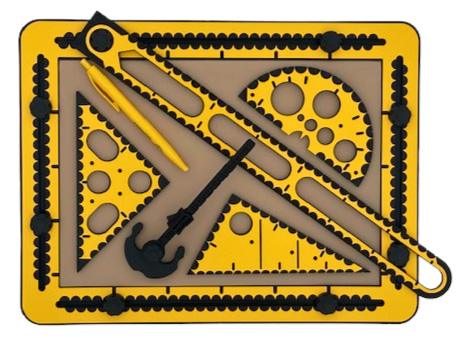
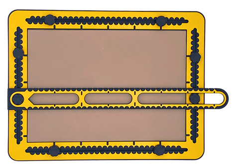
The TactiPad drawing board consists of a top frame that surrounds the A4 (21.0 x 29.7 centimetres) drawing area of the bottom layer. The two parts are connected with a hinge, so the frame can open like a book. The drawing board and tools are made of plastic. The corners are rounded. The total size is 28.0 by 36.7 centimetres. The use of the colours black and yellow for the TactiPad and the related products and tools provides a good contrast between different parts.
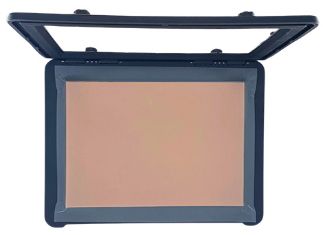
Photo: Drawing board with the top frame open, leaning backwards.
The frame has grooves in each of the four edges. Two knobs can slide in each groove. Measurement indications in centimetres are provided along the grooves. The drawing foil, which is a rather thin plastic foil is placed on the rubber mat, the actual drawing area. Underneath this mat, a metal plate is mounted.
When the frame is fully opened it can stand on its own so the drawing foil can be placed. Magnets pull the top frame and drawing layer together to keep the drawing foil in place. At the front side of the TactiPad, with the hinge pointing backward, the bottom layer is shaped inwards compared to the frame.
Detailed description
Natural dimensions and tactility
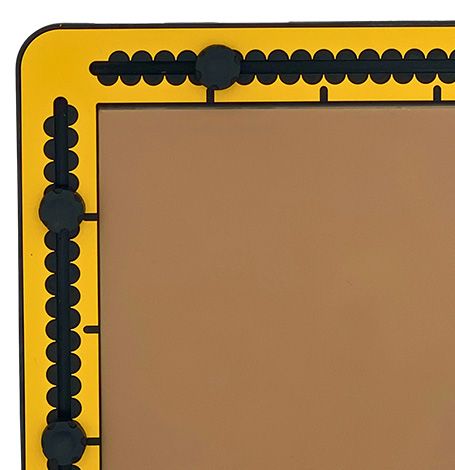
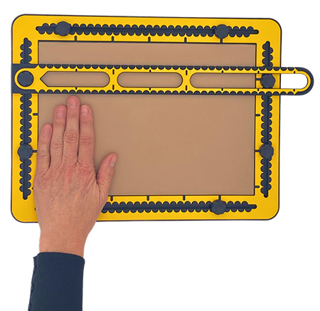
The dimensions of the drawing board and the tools have commonly used values. Knowing about these dimensions will help to get the distances ‘in your fingers’. The drawing area is A4. The width of the frame sides is 3.5 centimetres. The knobs in the grooves are two centimetres in diameter, with a height of eight millimetres. They are placed one centimetre away from the outer edge of the frame. Indents next to the drawing area indicate five- centimetre distances.
Photo: Detail of TactiPad drawing board.
Origin of the frame/0 centimetre position
Depending on the subject to be drawn, the drawing board may be used in landscape or portrait orientation. In both cases, the measurement indications start at the upper left corner of the drawing area. In landscape orientation, the centimetre indication goes from 0 to 29.7 centimetres horizontally. Vertically, it goes downwards from 0 to 21.0 centimetres. When the drawing board is in portrait orientation, the counting differs, due to the non-symmetrical dimensions of the A4 paper size. From the upper left corner to the right goes from 0 to 21.0 centimetres. Going down, the first indent is at 0.7 centimetre. Beyond this point, the regular centimetre pattern is present.
Grooves in the frame
The semi-circular hollows along the grooves indicate centimetre distances. The hollows on the inner side and those on the outer side of the groove have the same width but are shifted 0,5 centimetre. This allows rather precise measurement of 0.5 centimetre distances.
Knobs in the grooves
In every groove two movable knobs are mounted. Some of the TactiPad drawing tools, especially the ruler, can be attached to the knobs. While positioning the knobs, the tools can be positioned precisely.
Bottom layer/drawing area
The bottom layer has the same size as the top frame. On top of the bottom layer sits the drawing area, exsisting of a 4-millimetre-thick rubber layer. Underneath the rubber is, invisibly, a thin metal plate that pulls the magnets inside the compass base onto the drawing area.
Photo: The ruler placed on two knobs of the drawing board.
Drawing foil
The drawing foil is actually plastic foil. It is also referred to as drawing foil or German film. It measures 34 x 27 centimetres, and is tightened under the frame since it’s larger than the drawing surface itself. The magnets placed on the corners of the drawing board pull the frame and drawing layer together.
Note: Once the lines are raised, they cannot be erased. Also, the foi is sensitive to wrinkling so be careful by taking the foils from their pocket.
Cavities with magnets for the TactileView digital pen
In the middle of three edges of the frame, cavities can be found that are provided with two magnets. These magnets are used to position the frame for the receiver of the TactileView digital pen on the drawing surface. In combination with the TactileView Graphics editor. The TactileView digital pen product is discountinued since October 2022.
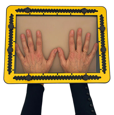
Place the drawing board in landscape orientation with the hinge pointing backwards. Slide your thumb under the top frame and place your fingers on the drawing area. Press on the drawing surface with your fingers. The magnets will release. The frame can be lifted. If you open the frame and let it lean slightly back, it stays in its open position. When closed, the frame exactly surrounds the drawing surface, and is just as high as the drawing surface.
Placing the drawing foil
In the open frame position you can place a drawing foil on the rubber mat. The foil is larger than the rubber mat. Make sure that the margins are roughly the same size on all sides. Close the frame and let it rest on the other hand. Smooth out the surface of the foil by moving both hands out from the middle to the sides while pressing the foil. Remove your hands and let the frame drop back into place. For best drawing results the foil should be placed on the drawing surface as smoothly as possible. You may have to practise this a couple of times to get a feel for it.
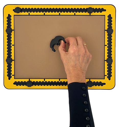
Photo: Removing hands from TactiPad after placing the drawing foil.
Drawing with the pen
The plastic foil that is used as drawing foil creates the raised line upon applying some force with a ballpoint pen or another pointed device. To acquire good skills for this, perform some practice. Read the manual section ‘Practising drawing raised lines’.
Positioning the knobs
The black ribbed knobs can be moved along the grooves by (un)screwing them. They can be removed by completely unscrewing them. To place a knob back in the groove, place it on a random place in the groove, and slide it all the way to the outer corner, dragging the nut along. Here, the knob can be screwed back in place.
Determining distances
As measurement indications in centimetres, 9-millimetre-wide semi-circular hollows have been made on a short distance from the edge. They create points between them, each with a distance of 1 centimetre to the next. With those points, it becomes easy to read the exact distance per centimetre. Because the hollows are semi-circular, the distance per 5 millimetres can be read in the deepest point of the hollow. After some experience it is possible to measure even smaller distances in the matter of millimetres.
Aligning the tools and frames
The drawing tools have holes and wide grooves to fit around the knobs. By fixing the knob and placing the tool over it, the tools can be tightened. With partially unscrewed knobs, the tools can move smoothly across the drawing surface.
An important aspect to keep in mind is the diameter of the knobs in reference to the centimetre indication. When aligning a tool on a knob, one centimetre has to be added or deducted to compensate for the knob. The CircleFrame and GraphGrid extensions have holes that fit around the knobs as well. The position for the knobs is about five centimetres away from the corner.
Drawing board picture frame
Two grooves have been made at the back side to make it possible to hang the TactiPad like a picture frame.
Your hands and fingers are the core of the toolset used to create raised-line drawings. For the TactiPad, they extended with additional tools such as a pen, a ruler, compass and many others. Probably they will execute new gestures and movements. So, it might well be that your hands and fingers can benefit from some training in order to perform drawing tasks as effectively as possible. The definition of ‘best’ is open for discussion, but aspects like speed, fluency and accuracy are certainly part of this.
In this text you find instructions and exercises to become better a free hand drawing. In the section measuring and drawing with a tool you find additional information to develop various drawing strategies. With these two sections we would like you to get to the point where you just grasp the pen and draw the subject of interest, without having to think on the “how-to” part.
Pen position
It is not easy to describe the ideal way to hold the pen in your hand. Here is an attempt, where it is assumed the pen is in your right hand. Take the pen in your right hand with the tip away from the hand. Bring the thumb, pointing finger and middle finger of your left hand loosely together so they form a triangle. Stick the pen tip into this triangle for about 1.5 to 2 centimetres. Your fingers will move away from each other.
Now place your thumb and pointing finger of your right hand against the tips of the left hand fingers. Naturally, the middle finger will also go to the pen. Now the tip of the pointing finger and the area near the first joint of the thumb hold the pen whereas the middle finger presses from the side against the pen. The pen is inside the three fingers of the right hand with the pen tip pointing left. The middle finger supports the body of the pen. In fact the thumb presses the pen against the fingers. This resting position can vary due to personal preference, but close to the nucle seems like a good position.
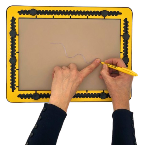
Photo: Raised line on TactiPad, with pen and finger.
Alternatively you can hold the pen in your fist, but it is harder to control the precision in your drawing because the movements come from your wrist and/or elbow.
Exercise: Drop the pen on the table and pick it up as quickly as possible. Follow the above instructions to position the pen in your hand. Place the pen tip on the drawing area. Repeat the steps 50 times.
Positioning your hand on the drawing board
When the pen is in your hand you can roll the hand off to the right. The right part of your wrist is now on the drawing board surface. The bone that is present here is a perfect support and turning point; the hand can swing and the fingers can move in and out. The combination of these two movements offers space for detailed drawing actions. Larger movements originate from the elbow and/or shoulder.
Exercise: Put your wrist on the drawing board and investigate which area you can cover with your hand and fingers while keeping the wrist at the same position. Use your left hand to get a feel for the distances.
Pressing on the paper; how much force
When holding the pen as described above, you can start drawing. Start somewhere near the top left corner so there is enough paper for the first exercises. Place the pen on the paper. The pen is in fact leaning over in the direction of your hand. Place your pointing finger of your left hand against the pen tip. Press down and drag the pen towards you. Your left hand pointing finger should now discover a raised line! This pulling operation is the easiest one.
Exercise: At this point you may test a few times how much force you need to apply to get the effect. Also, a different amounts of force results in different heights.
Please note, the lines that you get are not really soft. The paper has a miniature woven pattern that creates the raised line effect. When looking into the details, the line is not fully smooth. At first touch however it is a solid line.
Your name in large characters
When you know the shape of the characters of your name, it is a fun and useful exercise to write it a few times. Make sure the characters are at least two centimetres (approx 1 inch) high or more. Writing your name forces moving the pen in different directions and simultaneously keeping an equal force to maintain the height of the lines. Now pull and push operations are alternated.
Basic shapes
Time to move on to the next exercise; creating basic shapes that you need quite often. Exercise: Lean with the side of the wrist on the drawing board and draw the shapes with a size of 2.5 centimetres (approx 1 inch). Do not move with your arm while drawing one of the following shapes:
Short line
(Equilateral) Triangle
Square
Circle
Ellipse
You will experience an increased difficulty in this list. The images may be positioned next to each other or even partly overlap.
Drawing straight lines
The definition for a line is the shortest way between two points, but how to get this right? For short lines up to 5 centimetres (approx 2 inch) this can be done while keeping the hand in the same position.
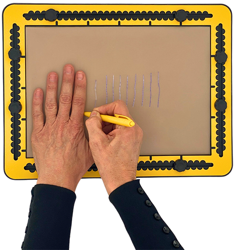
Using your finger as ruler. For a little longer line you could drag the pen alongside your finger. Just try this and you will be amazed how well this goes. Generally speaking it is recommended to keep the hand that is not holding the pen on the drawing board as well. At least when you are not using a tool.
Draw a line with a length of 10 centimetres (approx. 4 inch) between two finger tips is now possible. Find the begin and end position and place your thumb and pointing finger respectively. Determine based on your previous experience the direction on where to start the line (pulling or pushing the pen). For this distance the hand has to rotate together with the fingers that hold the pen. Use the, for you, highest speed to move the pen to keep the line straight. Lines of higher length require a tool like a ruler. However, in case they don’t need high accuracy, you can draw them with high speed, also moving your elbow.
Photo: The left-hand pointing finger used as a ruler while drawing short lines with your right hand.
After having created your first raised lines, there are a few more things we would like to bring to your attention. Some are just simply to keep in mind. Others will help to develop a variety of drawing strategies.
Orientation of the drawing board and horizontal/vertical lines
The word ‘orientation’ is used throughout the product descriptions and manual texts. When the drawing board lies flat on the table and the longest side goes from left to right, the drawing board is in landscape orientation. Make sure the hinge is pointing backwards.
When the shortest side is horizontal, the drawing board is in portrait orientation. The hinge should point to the left. Knowing the subject you want to draw, will lead to the orientation of the drawing board you choose. Apart from the orientation, lines drawn on the drawing board can be in the horizontal or vertical direction. Also, moving tools up/down and left/right within the drawing area is possible, independent of orientation. Knowing about distances; measuring and estimation.
Photo: The distance covered with four fingers measured with the ruler.
Knowing distances; measuring and estimation
The dimensions of the TactiPad and related products are based on measures that are commonly used. The reasoning behind this is that it becomes easier to get distances ‘in your fingers’, which will make your drawing actions more efficient. It is very helpful to know about the distance you can bridge based on the width of two, three or four of your fingers or the length of your pointing finger.
Play around with the ruler to find out how far you need to spread your thumb and pointing finger for particular distances. Exact measuring is best done with a dedicated tool, but a good estimation is good enough in many cases.
Measuring and aligning a tool
The measurement indications along the frame of the drawing board serve as the main reference for measuring positions across the drawing area. All tools have tactile properties that match these indications. Either with the semi-circular centimetre marks along the top surface, or with small indents along the edges of the tools.
Touching the surface with the fingers and/or listening to the tick sounds that occur when tracing the pen along the indented sides are two methods to ‘read’ distances. Where this is useful, the bodies of the tools have a width of one centimetre. So placing one tool adjacent to the other will maintain the regularly measuring system. See the detailed descriptions and manuals of the ruler and TactiForma tools.
Knob position and measuring along the drawing board frame
The unscrewed knob can be placed in an exact position by moving it against a finger that is crossing the groove while touching the measurement indication at the desired position. Keep in mind that the knob has a radius of one centimetre and the bodies of the tool also have their width. So you may have to add or deduct one centimetre to end up where you want.
Mark a dot with the pen or use pushpins
A drawing is never only one line from beginning to end. Curved lines and straight lines under various angles are connected. To mark the start and end position of a line you can press with the pen on the paper. A small tactile marking will appear. This marking can serve as a point of reference. You can use a tool to create a line between.
Two markings; you want the line exactly starting and ending at these markings. That means that the ruler may not cover the markings. Initially it takes some sensitivety to find them. Otherwise, you can place pushpins in the markings first. Than place the tool against the pushpins and draw the line between the two pushpins.
Tracing a pen along a tool
The tools are made of plastic and have a thickness of approximately 3.5 milimetres. The tip of the pen has a width of 1.5 milimetres and sticks out from the body only for a short distance. On closer inspection, the edges of the tools are rising up from the drawing area like a steep ramp. Even when the pen is in a fully upright position, the tip might not be exactly against the tool; the body of the pen prevents this.
Instead of a ballpoint pen you can use any other pointy device with a longer tip, but as we have seen before, fully upright is not the best position to hold the pen to perform the pull and push movements. When the pen is tilted away from the tool, the tip can go straight along the tool. This approach works well when using pushpins. When the pen is tilted towards the tool, the tip moves away from the tool, because the body ‘rolls’ off of the ramp.
Photo: Pen is tilted away from the tool.
Photo: Pen is in upright position against the tool.
Photo: Pen is tilted towards the tool.
You can use this effect to your benefit when working with marks on the paper. Place the tool just a short distance away from the marks so you still can find them with your fingers. You will get a feel for the tilting angle of the pen.
Drawing a straight line
Although we haven’t described the ruler or any other tool in detail up to this point, here is an approach for drawing a straight line. Starting in one of the (end) points and just draw onwards to the other, may cause the pen to pass by this position. To avoid this, find one of the two positions. Draw the line from here only partly in the direction of the other end point. Now start drawing in the other point into the direction of the first. You may draw a section of the line twice, but this doesn’t matter. Pushpins in both end points will serve as pen blockers; the pen will run against the pushpin that tells you to stop drawing any further.
Lines covered by a tool
Using a tool to draw lines and shapes bring in more accuracy and speed into the drawing process. The side effect is that the tool could cover part of the already existing lines, which makes it more difficult to find the exact begin/end positions. Therefore, it is worthwhile to look on which side of the foreseen line the tool is placed; left or right from the line.
Rotation and angles
In various manual sections you find instructions where tools are rotated over a number of degrees. The lowest/nearest side of the frame to you is the zero degrees reference. So from any position to the right, parallel to the frame is an angle of 0 degrees. Rotating counter-clockwise over an angle of 90 degrees results in a vertical line. Rotating 90 degrees clockwise as well. It is indicated what the rotation point of the tool is; either the centre of the tool or a corner. In some cases, you can use a pushpin as a fixed point for the rotation.
Photo: Four pushpins in the drawing board and in pushpin markers of the 45triangle.
Global description
The 10 pushpins are stored in a cushion in the carrying bag. The length is about 2 centimetres. The head of the pushpin is ball-shaped. The pin is made of metal.
Generally speaking, the use of pushpins will increase the overall accuracy of the drawing operations. On the other hand it takes time to handle the pushpins safely and efficiently Throughout the various manual sections the use of pushpins is explained. The usage of pushpins is based on your experience and preference and also on the accuracy you can get with or without the pushpins. Over time, your drawing skills will increase.
The pushpins are stored horizontally in their cushion. Take the head between thumb and pointing finger and stick it through the drawing paper into the rubber mat. Due to the flexibility of the rubber, the pushpins can waggle, but they won’t fall out. Don’t be afraid, they do not damage the rubber.
Markings and pushpins as reference points
By pressing with the pen on the drawing paper a raised dot will appear. In many cases this is sufficient as a reference point. In addition you can place a pushpin as reference point on the desired position or in the pre-made marking. Tools can lean against the pushpins. While drawing, also serve as pen blocker; the tip will bump into the pushpin. During measuring a distance certain points can be marked with the pen and/or equipped with a pushpin.
Pushpin markers
Many of the tools that come with the TactiPad or come as extensions, have so called pushpin markers. These are indented circles with a tiny hole in the middle at the top surface of the tools.
When one or two pushpins are stuck into the pushpin markers, the tools are fixed on the drawing board. For this approach the drawing process requires extra time, but the tools will for sure stay in their position.
Organising pushpins
You can take them one by one from the cushion. You could also use a magnet to organise them. A spare magnet can be stored in the small pocket in the carrying bag. The base of the compass is magnetic, so you can use this part to organise the pushpins.When holding the drawing board in landscape, in the middle of the left and right side and in the middle of the rear side cavities can be found. Here, magnets are located that can also hold the pushpins.
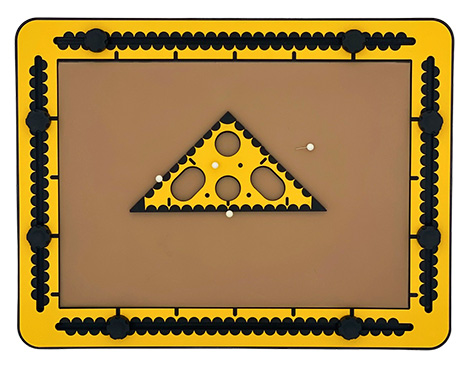
Create a triangle with markings and pushpins exercise
To experience the difference: Mark three positions somewhere on the drawing area with the pen. Use the slick side of the 45 triangle to connect the positions. An irregular triangle will appear. Measure the longest side of the triangle and mark the halfway position. Place a pushpin here. Place a pushpin in the opposing corner and draw the line between the two pushpins.
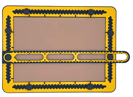
The ruler’s width is 4 centimetres, and has a lenght 43 centimetres long. At one end of the ruler, a 2 centimetre wide round hole is made. In the rest of the ruler there is a 2 centimetre wide groove.
The groove has two bridges; one at 10 centimetres, the next at 20 centimetres. Indents in the groove indicate a 5 centimetre distance in between. The ruler has measurement indications on both sides, for a length of 35 centimeters. One side has small indents along the edge every centimetre, the other side is slick.
Photo: The ruler placed on two knobs of the drawing board.
Especially for the ruler the knobs in the frame of the drawing board come in handy. They can be placed at any position in the grooves. With just the hole on a knob, the ruler can still rotate. In case the ruler’s groove is placed over a second knob, the ruler is fixed. For an exact horizontal or vertical alignment knobs have to be in equal positions in opposing grooves. When the ruler is horizontally or vertically placed, with the hole over a knob, the zero position of the ruler is on the edge of the drawing area.
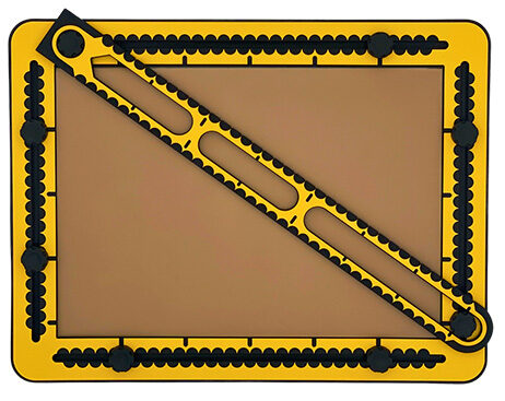
Diagonal lines
One of the two knobs in two grooves is placed at the very far end of the groove. For drawing a line at a precise position, take into account that the rulers edge is 1 centimeter wide.
The hole that fits around the knob is two centimetres wide and sits in the middle of the ruler. In other words positioning the ruler on a desired position is two centimetres higher or lower or left/right respectively, seen from the centre of the knob. Another method is to have the knobs partly unscrewed so they can move. Place the ruler on two knobs and slide the edge of the ruler to the desired position, using the measurement indications of the frame.
Photo: The ruler is positioned to draw a diagonal line on the drawing board.
Draw a (long) straight line
For many purposes it makes sense to have a horizontal and or vertical line as a start for a drawing. Whether it is the bottom line, the horizon or an axis. Find the horizontal and or vertical positions for knobs, draw the lines and remove the ruler from the knobs. For shorter lines you can use also the sides of the triangles as a ruler.
Aligning tools with the ruler
Leaving the ruler sitting on two knobs while placing other tools against the ruler’s edge, helps to add more lines/elements to the drawing. Aligning the tools of the TactiForma or the triangles that come with the TactiPad can be useful.
Photo: The 45 triangle aligned with the ruler, creating a bar chart.
X and Y axis/coordinate system example
It is assumed, the drawing board is in landscape orientation. Place the knobs in the vertical grooves at positions 9 and 11 centimetres respectively. Place the ruler over the lowest two knobs. Draw a line horizontally at 10 centimetres (the X axis) Everything above the ruler has a positive Y value.
Reposition the ruler on the two higher knobs and everything below the ruler has a negative value. Place the knobs at 14 and 16 centimetres in the horizontal grooves. Place the ruler on the knobs at 14 centimetres and draw a vertical line at 15 centimetres, the Y axis. Having the knobs in these positions and switching the ruler enables to align and measure for positive and negative values along both axes.
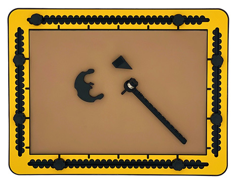
The compass is made up of two main parts: a beam and a base. The beam has a needle shaped turning point on one side and a pointy shape, the spike that can move along the beam. The spike produces the raised line of the circle. The needle slides into the centre of the base. The beam can move around the base in horizontal orientation clockwise and counter clockwise just above the drawing area.
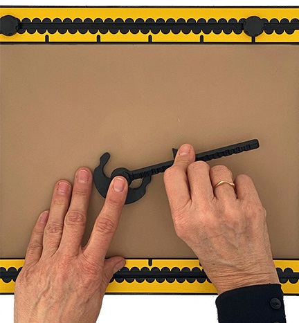
Photo: The three parts of the compass lying on the drawing board; the base, the beam and the spike.
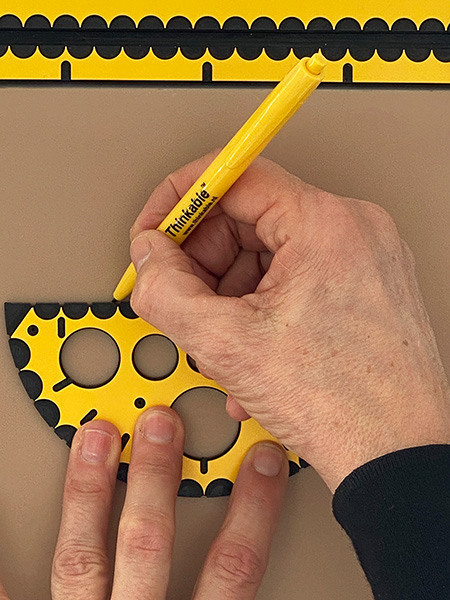
The base has a semi-circle shape with a diameter of almost 6 centimetres. If you want, you can see a rabbit face with two ribbed ears, two eyes, a mouth, a nose, and a arrowhead shaped hat, where one corner has been cut out.
In the centre of the base is the nose, the hole that holds the needle/beam upright. Along the outer edge of the base, three semi-circular hollows have been made. According the face analogy; one at the bottom, the mouth and the eyes near the ears. One half of the arrowhead is cut off. At the bottom side the base has three strong magnets and five anti slip feet. With this combination the anti-slip effect is really high.
Photo: Close up of the base, two fingers holding one of the ears.
Compass beam
The beam has a total length of about 13 centimetres. Three small ramps at the top side are present to indicate the smallest radius of three centimetres. From here on indents per half centimetre can be found. The maximum radius of the circle can be set to 12 centimetres. The beam has a ring on one side that encloses the needle in a ball mount. This enables the beam to be lifted or tilted during rotation. The needle could be described as a mushroom. The ribbed head on top is sitting on a metal ball that is surrounded by the ring. The needle continues below the ball. At the end three small spikes can be found.
Spike
A ribbed, open block can move along the beam. It will click into the indents so it stays in position. Underneath the block is a triangular shaped that is the actual ‘pen’ that draws on the paper.
The beam and spike are assembled together in an elastic tube. Remove the spike from the beam so you can take the beam from the tube. Re assemble the two parts. Make sure the right side of the spike is facing the needle. For now, move the spike fully over the beam towards the needle. The compass base is stored separately. It is held in place with two elastic bands over the ears. Fetch the band and enlarge the opening to take out the ears one by one.
Photo: Compass beam stored in the carrying bag.
Magnetic force
The base has strong magnets so it adheres to the metal plate underneath the rubber mat of the drawing board. When placing the base on the drawing board you will experience the magnetic effect right away. The base will slide not slide easily.
Removing the base from the drawing board becomes easy when lifting the base at one ear. Be aware, it can attach itself to other metal objects whenever the distance is small enough.
Adjusting the radius
Before assembling the compass, play around with setting the radius to particular values. Therefore, hold the needle’s side of the beam in one hand and take the ribbed spike between thumb and pointing finger and move it in steps to the desired position. You will recognise the clicks while moving. Check the radius by counting along the beam, starting at the three centimetre starting block indicated with three small ramps on the beam.
Draw your first circle
Set the radius for the circle at six centimetres. Choose a position for the base somewhere in the middle of the drawing board. Put the needle in the centre of the base. The spike will rest on the drawing paper.
Lift the beam while rotating so it is pointing away from you. Place the pointing finger of the left hand on the needle’s head and hold it steady. The thumb and middle finger can hold the base. Take the spike between your thumb and pointing finger of the right hand. By nature the beam / spike will tilt towards you when you drag the pointer towards you while pressing down as well. Remember the pull operation for smooth drawing.
Photo: The compass is placed on the drawing board. The needle is supported with a pointing finger and the spike is held between thumb and pointing finger of the other hand.
The contour of the circle will rise up behind the spike. While dragging/rotating the beam with spike, at some point you will run against the hand that keeps the needle in place. Now take your hands off and let the compass sit in its position. You can change hands now; the pointing finger of the right hand will now support the spike. The left hand will take over. Continue the drawing operation to the point where you started drawing. The magnets in the base ensure the base will stay in its position. It doesn’t matter if you redraw part of the circle.
Indication for the centre of the circle
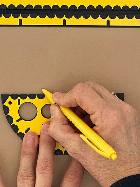
The bottom end of the needle has three very small spikes. When you press and turn the head on top, without moving the whole beam, a small tactile circle is created, indicating the centre of the circle drawn. Placing the compass base on a particular position. The arrowhead can be used to precisely place the centre of a circle on a specific point in the drawing.
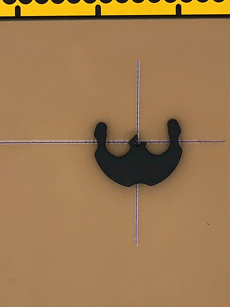
Mark this position with the pen or place a pushpin. Move the centre hole to the mark and align with the sides of the arrow head. If you place the corners of the arrowhead on two crossing lines, the compass needle is exactly on the crossing.
Photo: The compass base with the centre on crossing lines.
The alignment indents around the outside of the base can be used to precisely position the centre of the circle on a line. Check with the fingertip if the middle of the two eyes is on the line. The centre is already on the line. Check if the middle of the mouth is also on the crossing line. The centre is now on the crossing.
Fantasy – clock
Draw a circle with a radius of six centimetres. Draw a second circle with a radius of 7.5 centimetres with the exact same centre position. Start with the smaller of the two circles. Leave the base sitting in its position. For the larger one take the base between your finger tips and press it down so when you pull the spike to its next position, it does not move. Draw the circle and check if the distance comes out equally all along. Provide the space between the two circles with small lines by freehand as indicators for the hour positions.
The triangle with the two 45 degree and one 90 degree corners is referred to as the 45triangle. The rectangular 45triangle has the same measurement indication as the drawing board. The two short sides have a range of 10 centimetres, while the long side has a length of 14 centimetres. There are four holes in the triangle for fixing it over the knobs of the drawing board.
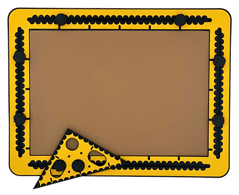
Photo: The 45 triangle aligned with a side of the frame.
At a distance of one centimetre from the right corner a hole is made. In the middle of the long side, one centimetre distance to the edge, a hole is made. To the left and right are two long holes. Along the short sides small indents per centimetre are present. The long side (hypotenuse) is slik. Small grooves in the top surface indicate distances of five centimetres. Pushpin markers are available.
Basically all tools that have a straight side can be used as a ruler. It is a matter of preference and which tool is most handy. The slik side of the 45triangle is sometimes preferable because tracing the pen tip along an indented side causes interruptions.
Using the knobs in the drawing board frame
The round hole in the 90 degree corner fits around a knob. Aligning one of the short sides of the triangle with the edge of the frame, makes two angles on the board, one of 90 and one of 45 degrees.
When putting the hole in the middle of the long side and one of the others over a knob, an angle of 30 or 60 degrees can be made by turning the triangle to its extreme position.
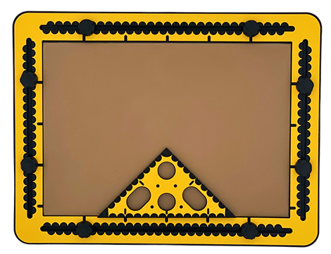
Photo: The hole in the middle of the long side on a knob and one of the oblong holes on a second one. The 45triangle is rotated.
Bar chart example; 10 centimetres stands for 100%
Place the drawing board in landscape orientation. Place one of the knobs in both vertical grooves 16 centimetres from the top. Add the ruler onto the knobs. The edge is now at position 15. Draw a line.
Align the 45triangle
Find the five centimetres position of the ruler. Align the short side of the triangle with the ruler so the 45 degrees corner is pointing to the right. Draw a line along the vertical side of the triangle. Start at position 10 and draw the line downwards, on to the ruler. 10 centimetres represent 100%. While the tool is still in place, mark positions 2,5, 5 and 7,5 with the pen. Move the triangle two centimetres to the right (position 7) and draw a line starting at five which represents a value of 50%. Create more bars where one centimetre stands for 10%. Horizontally there is enough space to create bars for the 12 months of the year. With a spacing of two centimetres you can add a character or a mark below the bar to indicate a specific bar.
Please note: Bar charts generally have two lines that make up for one bar. Here the bar is only one line wide. The space between the bars is there to distinguish one from the other.
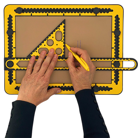
The triangle with 30, 60 and 90 degrees corners is referred as the 30triangle. When the three corners of the triangle are set to 30, 60 and 90 degrees respectively, it is known as a ‘1/2/sqr(3) triangle’. As a given, the three sides always have these proportional lengths. For practical reasons, the longest right side (sqr(3)) of the triangle tool is set to 15 centimetres (about 6 inches). The length for the other two sides can then be calculated as 15/sqr(3) multiplied by 0.5 or 1 respectively. (8.66 and 17.3 centimetres). The 30 degrees corner is pointing to the left when the surface with the tactile measurement indications is facing up and the 90 degree angle is at the bottom right.
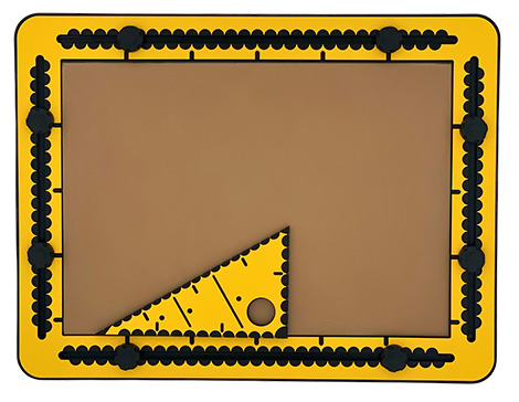
Photo: The 30 triangle with the 30 degrees corner pointing to the left.
For the two sides connecting at the 90 degree corner, the measurement indications are in centimetres. The distance between the units along the hypotenuse is somewhat arbitrary! For the 30triangle it was decided on 20 units spread over 17.32 centimetres, which is rounded 0.87 centimetre per unit. With this regular pattern it is easy to count/measure from both the 30 and 60 degrees corners onwards in groups of 5 units. The measurement indications at the top surface of the triangle are semi circles. At each measurement unit also a small indent is provided. Per five units a short groove at the top surface is provided for easy counting.
As a tactile guidance, when following the two long narrow grooves in the top surface, they are pointing to equal positions on the longest right side and the hypotenuse. A hole of two centimetres can be found near the 90 degree corner. It can be used to place the triangle over one of the black knobs in the TactiPad frame. Pushpin markers are available.
Considerations for the design
In the design story you can read about the practical approaches that were taken to determine the measurement system for the hypotenuse. The insights may help to utilise the tool.
The hole near the right corner can be placed around one of the knobs. Aligning one side of the 30triangle with the side of the frame offers a 60 or 90 degrees angle in reference to the paper edge.
3D coordinate system
Put the drawing board in landscape orientation. Draw a vertical line at 10 centimetres and a horizontal one at 15 centimetres. Align the triangle with the ruler where the 30 degrees corner is at the crossing of the two lines. Draw a line along the hypotenuse. In a 3D coordinate system the hypotenuse is the X axis. The longest side aligned with the horizontal line serves as the Y axis. The vertical line is the Z axis. You can decide if you want to use any measuring system along the axes.
Draw a cube with sides eight centimetres; exercise
Note: In this exercise no coordinate system is used.
Maybe having a die is handy to imagine the below. In total 12 lines are required to form the cube. The eight corners are named A, B, C and D for the bottom surface and E, F, G and H for the top surface. The corner E is positioned above corner A. The line A-B is horizontal and going to be nearest to you. For the length of the sides eight measurement units are taken; centimetres or the small ones along the hypotenuse. The order in which the lines are drawn may seem illogical, but moving the tools around is minimised.
Steps to take:
Step 1: Place the ruler at 15 centimetres horizontally in order to make sure the lowest side of the front face is horizontal in reference to the paper’s edge.
Step 2, rib A-E: Find the position five along the ruler. Place the 30triangle against the ruler with its right corner pointing to the right here. Draw a line along the triangle’s short side downwards from the eight position on to the ruler.
Step 3, rib A-D: Shift the triangle to the right until the 30 degrees corner is at the A corner. Hold the triangle tight against the ruler. Draw a dashed line spanning eight units along the hypotenuse. Make sure there is at least a line fraction at corners A and D.
Step 4, rib A-B: Draw along the ruler for eight centimetres from the corner A, the point where the rib A-E touches the ruler.
Step 5, rib B-F: Move the triangle’s right corner to the right over eight centimetres to the end of the line A-B. Draw the line from the eight position downwards on to the ruler.
Step 6, rib B-C: Move and align the triangle further to the right until the 30 degrees corner is at corner B. Draw for this rib a solid line with the length of eight units along the hypotenuse.
Step 7, rib C-D: Move the ruler up as far as the line endings of the lines A-D and B-C just peep out from underneath the ruler. Find corner D, draw a dashed line to the right to corner C. This completes the bottom face of the cube. (A-B-C-D)
Step 8, rib D-H: The ruler is already in a good position. Place the triangle with the right corner at corner D and draw a dashed line along the triangle from the eight position downwards on to the ruler.
Step 9, rib C-G: Move the triangle to the right until the right corner of the triangle is at corner C. Draw a solid line from the eight position downwards on to the ruler. At this stage only the top face has to be finished.
Step 10, rib E-F: Move the ruler up until the end points of the lines A-E and B-F peep out from underneath the ruler. Create a line between the two endpoints of the vertical ribs. The front face is ready.
Step 11, rib E-H: The ruler is again in a good position. Place the 30 degrees corner at corner E while holding the triangle against the ruler. Draw a solid line with a length of eight units along the hypotenuse. Corner E and H do exist already.
Step 12, rib F-G: Move the triangle to the right, place the 30 degrees corner at the F corner. Draw a solid line along the hypotenuse with a length of eight units. The right hand face is completed.
Step 13, rib G-H: Move the ruler up and connect the two line endings at corners H (left) and G (right).
You are done!
Using a 3D coordinate system for a cube
Once a 3D coordinate system is created, a few of the ribs are already available. There are two options to choose from: Corner A at the position where the three axes cross or corner D at this position. In case A is at the crossing, corner E is on the vertical (Z) axis. Otherwise you find corner H here. Drawing a cube can be performed with a square tool faster. See the manual section on the TactiForma square tool. The grid boxes provided by the GraphGrid enable indicating the corners of the cube. Or other 3D figures. The motorised drawing arm (MDA) is even faster. In addition it enables to draw the cube in any rotation angle over the X, Y or Z axis.
We use cookies to ensure that we give you the best experience on our website. If you continue to use this site we will assume that you are happy with it.