06 Regular polygon tool

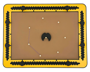
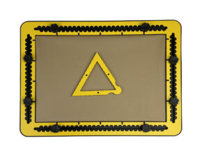
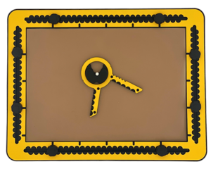
The five sided regular polygon tool, holding the magnetic foot with pushpin.
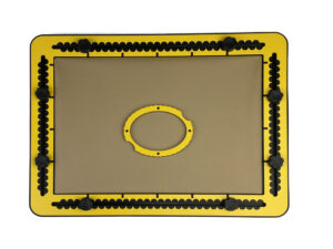
Photo: Lens tool for convex, concave and mirror on the TactiPad.

The TactiForma set contains regular polygon tools with five, six, seven, eight or nine corners referred to as pentagon, hexagon, heptagon, octagon and nonagon respectively. The radius of the polygons range from three to eight centimetres. The magnetic foot is an essential part of the regular polygon tool, to hold the tool in place.

To description section
To manual section

Global description

Imagine a line drawing of an isosceles triangle pointing upwards. The top is cut off and replaced by a circle (a ring). The base line does not exist. The length of the two sides that stick out from the circle (the rulers) determine the maximum radius the polygon can have.

Detailed description of the polygon tool

The sides are a-symetrical connected to the ring; the right ruler goes along the outer side of the triangle, the left ruler along the inner side. Where both rulers would meet in the top corner, the top is cut off and replaced with a ring, so the rulers are only partly present. The rulers have a centimetre indication at the top surface and along the side indents at every half centimetre. The measurement indications point in the same direction. They have a pushpin marker near to the ring and at the end of the ruler.

At the outer side of the right ruler, medium sized indents are provided to indicate the type of polygon. E.g. six indents means the hexagon polygon tool. The hole in the ring leaves space to find the centre position of the polygon and is also the fit for the magnetic foot to hold the tool in place during the rotation of the tool.

The ring has an inner radius of nearly two centimetres and an outer radius of nearly three centimetres. This enables a radius for the polygons ranging from a minimum of three centimetres and a maximum of eight centimetres. Three small indents are at the outside of the ring. One of them is placed on the line formed by the bisector. Two others on an orthogonal line that crosses the centre position. The round foot has two magnets fully encapsulated in rubber, to hold the body of the tool in place. It is lacking a section so the fingertip can slide in. This open area is called finger entrance. It enables exploring the drawing near the polygons centre area. The vertical groove in the middle of the finger entrance Can hold a pushpin and indicates the precise centre position of the polygon.

Remarks

Knowing about regular polygons; a shape based on triangles. A regular polygon is a shape where the individual sides are all of the same length. It can also be described as a circle filled up with isosceles triangles. The sides of two adjacent triangles co-inside. However, the sides of the triangles are not present in the drawing. Only the base sides are visible as the sides of the polygon shape. For the drawing instructions: Each triangle of the regular polygon is called a segment.

The angles for the respective top corners of the pentagon, hexagon, heptagon, octagon and nonagon are 72, 60, 51, 45, and 40 degrees.

Regular polygon tool manual

To description section

Although the corner positions can be marked with a dot only, the use of pushpins is recommended.
For the first segment, place a (pointing) finger on the desired position in the drawing area and move the foot with the finger entrance against the fingertip. Place the ring of the tool over the foot. Determine by rotating the tool, the orientation for the first segment.

Decide on the radius of the polygon and place a pushpin in the corresponding indent of both legs. For the second segment: Rotate the tool slightly off from the pushpins and lift the tool and rotate further in any of both directions until the legs have passed the pushpins. Slide the tool back against the pushpin and place another pushpin in the appropriate radius position in the unmarked leg. Repeat this till you are back at the starting point.,

A seven cornered polygon with pushpins at all corner positions. One side is connected, the next is to be draw with the rectangle hook tool placed against two pushpins. The pushpin indicating the centre is also present.
Photo: A seven cornered polygon with pushpins at all corner positions. One side is connected, the next is to be draw with the rectangle hook tool placed against two pushpins. The pushpin indicating the centre is also present.

After creating all the segments you can remove the tool and the magnetic foot and connect the pushpins/corners with straight lines. In addition, by leaving the pushpin in the centre one or more radii can be drawn. The rectangle hook tool placed against the centre pushpin and one of the corners, enables you to draw a radius.

More precision with alignment

Place a pushpin first to mark the centre position in case this is relevant. Move the magnetic foot so the groove in the finger entrance embraces the pushpin.

Aligning the polygon tool with existing lines

The ring has small indents for alignment of the polygon with a line. Placing the bisector indents on a line, the centre will be on that line. The segment is cut in half. Placing the orthogonal indents on a line puts the centre on the line and ensures the side of the segment is parallel to the line.

Spider web

For a sophisticated spider web use different polygon tools. Create a few – slightly shifted – concentric polygons on the TactiPad and draw lines through the corners. See what happens when the more cornered polygons are at the outside of the web.

06. Ellipse Tool

Detailed description of the ellipse tool

The body of the tool is symmetrical. It can be seen as a circle, equally stretched in 2 opposite directions. The frame of the tool is one centimetre wide. At the outer side the frame has 2 finger fitters for easy grip.
Pushpin markers are located at 0, 90, 180 and 270 degree angles relative to the centre position. So the markers indicate the longest and shortest diagonal of the tool.
As the TactiForma ellipse is a circle based shape, radii can be drawn from the centre. Indents per 10 degrees along the outside indicate the angles.

For more information, have a look at the Ellipse Tool Manual page.

05. Spur Wheel

Detailed description of the spur wheel tool

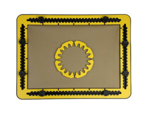
The wheels in the set have 12 and 20 teeth respectively.
The body of the spur wheel is a circle with eight finger fitters around the outside. The body width is about six millimetres. From this inside circle the ‘negative’ teeth are pointing towards the centre.
After tracing the inner contour, the spaces between the teeth are in fact the positive teeth around the outside of the spur wheel.
Pushpin markers are located in the top surface of the body.

For more information, have a look at the Spur Wheel Tool Manual page.

04. Polygon Tool

Detailed description of the polygon tool

The TactiForma set contains tools to create regular polygon shapes with five, six, seven, eight or nine corners referred to as pentagon, hexagon, heptagon, octagon and nonagon respectively.
The radius of the polygons range from three to eight centimetres.
The magnetic foot is an essential part of the regular polygon tool, to hold the tool in place.

Foreword
The regular polygon shape and the regular polygon tool itself need some more explanation than other TactiForma tools for a good understanding. Especially the regular polygon section in the design story of the TactiForma provides more background about the design requirements.
In order to use the regular polygon tool, using pushpins is recommended.

The regular polygon shape based on triangles
A regular polygon is a shape where the individual sides are all of the same length.
It can also be described as a circle filled up with isosceles triangles. The sides of two adjacent triangles co-inside. The sides of the triangles are not present in the drawing. Only the base sides are visible as the sides of the polygon shape.
For later on: Each triangle of the regular polygon is called a segment.

Global description of the tool
To understand the setup of the tool, imagine a line drawing of an isosceles triangle pointing upwards. The base side is horizontal. The top corner is above the middle of the base side. The angles for the respective top corners of the pentagon, hexagon, heptagon, octagon and nonagon are 72, 60, 51, 45, and 40 degrees.
The top of the triangle is going to be the centre of the polygon. The tool is rotating around this centre point while shifting from one segment on to the next.
The two sides of the triangle are in fact the rulers to measure and set the radius of the polygon.

Body of the tool
Keep the triangle from above in mind. The equal sides of the triangle are rulers, the legs of the tool. An important detail; the right ruler goes along the outside of the triangle, the left ruler along the inner side of the triangle. In effect the rulers are placed asymmetric. This comes in handy when drawing. See drawing instructions.
Both rulers would meet in the top corner, but a top section of the triangle is cut off and replaced with a ring, so the rulers are only partly present.
The hole in the ring leaves space to find the centre position of the polygon and is also the fit for the magnetic foot to hold the tool in place during the rotation of the tool.

Tactile properties
The legs have a centimetre indication at the top surface and along the side indents at every half centimetre. At the outer side of the right leg, medium sized indents are provided to indicate the type of polygon. E.g. six indents means the hexagon polygon tool.
Seen from the centre point, the ruler goes from three to eight centimetres.
Each ruler has a pushpin marker near to the ring and at the end.
The ring has an inner radius of nearly two centimetres and an outer radius of nearly three centimetres. Three small indents are at the outside of the ring.
One of them is placed on the line formed by the bisector. Two others on an orthogonal line that crosses the centre position.
The round foot has two magnets fully encapsulated in rubber, to hold the body of the tool in place. It is lacking a section so the fingertip can slide in. This open area is called finger entrance. It enables exploring the drawing near the polygons centre area.
The vertical groove in the middle of the finger entrance indicates the precise centre position of the polygon. The groove can partly surround a pushpin.

For more information, have a look at the Polygon Tool Manual page.

03. Rectangular Hook Tool

Detailed description of the rectangular hook tool

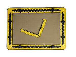
The rectangular hook tool has the shape of a capital l, where the horizontal and vertical part of the character have the same length of 10 centimetres / approx. 4 inches.
The two parts enclose an angle of 90 degrees. They are equipped as a ruler with measurement indications in centimetres at the top surface and indents per half centimetre along the sides.
The body of the tool is two centimetres wide. On the outer side, near to the rounded corner and to the tips you find finger fitters for easy lifting or extra grip.
The corner between the sides is rounded at the outer side. At the top surface is a groove under an angle of 45 degrees for alignment.
The rulers are ending with a 90 degree hook serving as a pen blocker.
Pushpin markers are located near the rounded corner and near to the tips.

For more information, have a look at the Rectangular Hook Tool Manual page.

02. Triangle Tool

Detailed description of the triangle tool

The length of the sides range from three to nine centimetres. The body of the triangle is about 12 millimetres wide. On all three of the outer sides a finger fitter is provided for easy lifting or extra grip. One outer corner is rounded, the other two are sharp. All three corners have a pushpin marker at the top surface.
Along the outside and inside are indents located at every centimetre. They align with each other. In case the length of the side is odd numbered, there is an indent in addition at the halfway position.

For more information, have a look at the Triangle Tool Manual page.

01. Square Tool

Detailed description of the square tool

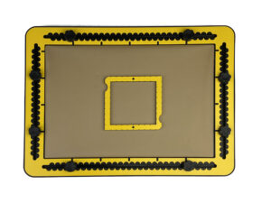
The sizes of the squares ranges from two to eight centimetres. The frame that forms the square is one centimetre wide.
Two finger fitters are provided in opposing sides. Two opposite diagonal corners are rounded. The others are sharp. At each corner a pushpin marker is located.
Along the outside and inside a small indent is provided at every centimetre.
In case the length of the side is odd numbered, there is in addition an indent at the halfway position.

For more information, have a look at the Square Tool Manual page.

Designing 30/60/90 degrees triangle tool for the TactiPad

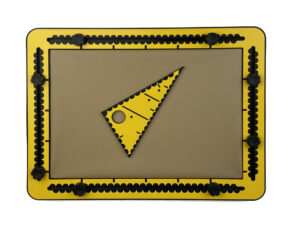
A math teacher came to us with the question: ‘Can you create a 30/60/90 degree version of a triangle tool for the TactiPad’? He wants his students to draw 3D shapes such as cubes, prisms and pyramids. Being interested to improve/extend the Thinkable products we have taken up this challenge.

After describing the details of the tool, we present some of the decisions we made during the design process. You will also find information on some of the aspects of the creation of ‘3D space’ using the TactiPad.

Read more

Jaap Breider introducing Eskandar Abadi to tactile graphics

In late summer 2021, Thinkable CEO Jaap Breider was visited by journalist Eskandar Abadi and film maker Shahab Kermani. They produced a video for Deutsche Welle TV (Persian department). Jaap was accompanied and interviewed during one day in his house and company headquarters in Huissen (NL).

Besides receiving his guest, talking about himself and Thinkable, Jaap explains the basics of tactile graphics to the interviewer. Being a blind man himself, he is obviously experiencing something completely new: Jaap draws or plots graphics for him while he also explains the “codes” behind certain ways of drawing from the seeing world.

It is these kinds of moments that keep Jaap inspired since decades. With Thinkable, he constantly works on innovations to give ever more VIPs access to tactile graphic information.

Video link: https://www.youtube.com/watch?v=ho_Lg3yekKE

TactiPad – Drawing tools – Art & Science Templates: Spur Wheel

The Spur Wheel Template

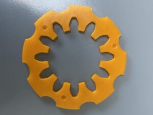
Photo: Spur wheel with 12 teeth
Photo: Spur wheel with 12 teeth (prototype 3D-print)

Detailed description of the spur wheel template

There are different types of spur wheels. This shape represents the mechanical properties with which the force can be maximised. When you interlink two wheels of this type, their teeth always have a point of contact under an angle of 90 degrees when rotating. Although it looks like an arbitrary number of teeth can be placed in a circle, this is not the case.

The wheels in the set have 12 or 15 teeth respectively. The spaces between them – their negative counterparts – are placed on the inside of the round template, so that the drawing result will have its teeth on the outside. The body of the spur wheel has finger fitters in eight positions along the outside for easy lifting or extra grip. You find pushpin markers in the top surface of the body.

Utilising the spur wheel template

The spur wheel is a relative complex tool to use / shape to create. We recommend to use one to two push pins to fixate to tool on the TactiPad. Draw the inner contour of the spur wheel and you have created the first step into the mechanical domain or flower design.

Once you have interlinked two spur wheels, you will experience a complex issue: finding the perfect position for one tooth on the one and two teeth on the other wheel to “bite each other”. This gives you an impression of how delicate spur wheel systems are in mechanics.


    What do you think about this? Send us some quick feedback!

    Thoughts? Recommendations? Questions? Just enter some text and submit. If you'd like us to reply, please include your email address.

    Item added to cart.
    0 items - $0.00