Global description
The symmetrical tool could be described as a traditional house where the top part is curved. The first floor is one big window where to top side is curved. The second floor has a window where the top and bottom sides are curved in opposite directions.
The shape of all curves represent the curves of the lenses.
In the top and bottom sides of the tool small indents are provided to align the tool on the median light beam.
Pushpin markers are provided at the top surface.
Detailed description
The inner space of this U-shaped tool has the contour of the formula X to the power of two.
The two poles of the U have indented centimetre indications along the outside.
Three medium size alignment indents are provided near the bottom; one in the middle and one in each of the two poles.
Pushpin markers are provided in the top surface of the tool.
The contour of the graph goes down and up again. At the two ends of the contour pen blockers are provided.
Indented positions along the curve reflect Y values for X equals -2, -1, -0,5, 0, 0,5, 1 and 2.
SinTang; combination tool for the sine, cosine and tangent graph
Global description
The SinTang tool combines graphs for two formulas; the sin(X) and the tan(X). More precise, a half period of the sine graph and a quarter of the tangent graph.
The sine graph, is the ‘hill’ contour which is the first half period of the sine graph. The cosine is a to the left shifted sine graph.
When placing the tool looking at the hill, the top side of the tool is a left to right downhill slope. After rotating 90 degrees clockwise it represents a quarter of the tangent graph.
The vertical left and right hand sides have an indented centimetre indication.
Pushpin markers are provided at the top surface.
For sine and tangent values of 1, the distance along the Y-axis is 4 centimeters. These dimensions provide sufficient ‘tactile space’.
Detailed description of the sine tool
The range from 0 to 180 degrees X values is distributed over a length of eight centimetres (aprox. 3 inches).
At 90 degrees is the top of the graph (maximum amplitude) at an height of four centimetres.
Small indents are provided in the curve at 30, 45, 60, 90, 120, 135, 150 degrees positions.
Pen blockers are provided at 0 and 180 degrees positions.
Detailed description of the tangent tool
To use the tangent part of the tool it has to be rotated for 90 degrees clockwise.
The contour of the tangent has small indents indicating the 30, 45 and 60 degrees positions on the X axis. The tan(45) is 1. The value of the graph is 4 cntimetres.
Pen blockers are provided at the 0 degrees and towards the 90 degrees position.
A length of four centimetres along the X axis covers a range of 90 degrees.
Sine graph
Photo: The first half of the sine graph has been drawn, the tool is rotated 180 degrees so the second half can be created.
Draw an X axis with the ruler. Mark the X=0 and X=180 degrees position. The distance between the two marks is eight centimetres.
Align the two two centimetre indications of the tool with the X axis.
Draw the contour line for the sine from the X value of 0. Start at the pen blocker to avoid glitches. Draw along the contour until the pen blocker at the X value of 180 degrees which is on the X axis. Hold the pen on this position and rotate the tool around this pen position so the tool is upside down. Continue drawing the second half of the tool until reaching the pen blocker again on the X axis.
For convenience place a pushpin at the 180 X position and rotate the tool around the pushpin.
You can also place pushpin(s) in the pushpin marker positions to hold the tool in place.
Cosine graph
Photo: The first quarter of the cosine graph is drawn. The tool is rotated 180 degrees clockwise, so the ‘hill’ is upside down for the negative part of the graph.
Basically the shape of the cosine has the similar shape as the sine. However the graph is shifted to the left for 90 degrees.
Draw an X axis with the ruler. Mark the 0, 90 and 180 degrees positions. A section of 90 degrees has a length of four centimetres.
Align the tool with the X axis where the right pen blocker is positioned at the 90 degrees position. Draw along the contour starting at the top (X=0) downwards to the X axis.
Rotate the tool 180 degrees clockwise. Align the tool with the X axis and draw the negative part of the graph from 90 to 270 degrees.
Rotate the tool once again. Align the tool with the X axis and draw the last quarter of the graph up from the X axis on to the top of the graph.
Tangent graph
Photo: The X and Y axis are drawn as well as the first quarter of the tangent graph. The tool is positioned so the second quarter can be created. The pen blocker is hooked with a pushpin.
Draw an X axis with the ruler. Mark the 0, 90, 180, 270 and 360 degrees positions. The distance between each position is four centimetres, which covers 90 degrees.
Draw two asymptote lines : One at 90 degrees and one at 270 degrees.
The distance for the first asymptote line is four centimetres from the 0 degrees position on the X axis, the next one is at a 12 centimetres distance.
For the first section of the graph align the short (four centimetres) side with the X axis. Start at the pen blocker (0 degrees) and draw along the tangent contour upwards until you approach the first Y axis.
For the second section of the graph find the 180 degrees position (preferably provided with a pushpin).
Hook the pen blocker with the pushpin while the tangent curve is pointing down. Align the tool with X axis and draw the lower part of the graph.
For the third section rotate the tool around the pushpin 180 degrees counter clockwise. The tool has the same position as for the first section.
The fourth section is similar to the second section. Find the 360 degrees position, hook the pen blocker to the pushpin and align the tool with the X axis and draw the curve going down unstill you approach the Y axis.
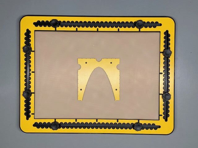
Parabola manual
Photo: A parabola has been drawn at X=0 and Y=0. The tool is positioned to create a second one at X-3 and Y=2.
Draw an X and Y axis.
Align the bottom indent with the Y axis and the ones in the poles with the X axis.
Draw along the contour of the tool.
You may choose any other coordinate as the minimum for the y value. The centimetre indications help to align the tool with the axes.
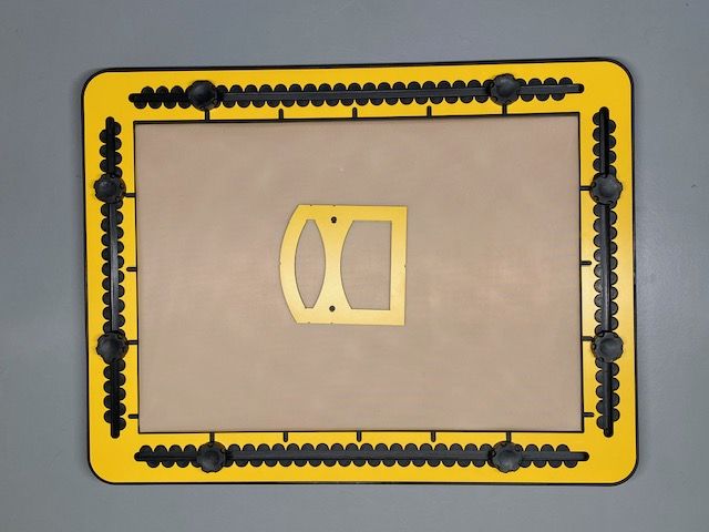
Lens manual
Photo: for the application the tool is rotated 90 degrees. The median light beam is drawn. A convex lens has been drawn. The tool is positioned to create the mirror.
Draw a line with the ruler to represent the median light beam.
Align the tool on the line.
Draw the inner contour for the mirror, the convex or the concave lens.
You can add additional light beams to show light breaking and reflection effects.
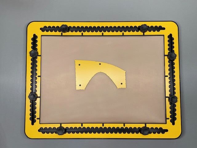
Hyperbole manual
Photo: An X and Y axis are drawn. The graph is drawn in the first quadrant. The tool has been rotated 180 degrees clockwise so the second part can be created. A pushpin is at position X=0,Y=0.
Draw an X and Y axis with the ruler
Be aware, the effect of the additional material is also that the actual X and Y axis are covered by the tool.
Align the tool with the two axis by placing the flat sections at the tails with the axis.
For convenience you can place a pushpin in the crossing of the X and Y axis.
Draw along the contour of the tool.
Rotate the tool 180 degrees clockwise. Align the tool with the axis and draw the second part of the graph.
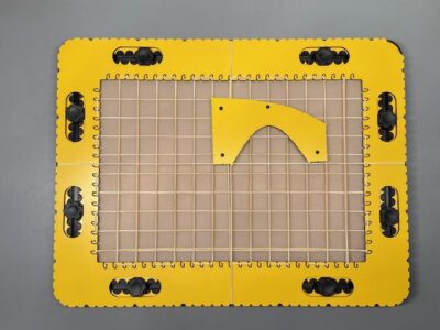
Preparation
The default setup has rubber bands every two centimetre in horizontal and vertical direction, so forming a grid.
Two rubber bands go around the frame to indicate two axes.
However, before mounting the GraphGrid frame on the TactiPad make sure all rubber bands are provided according your preference.
Low and high rubber bands – Using differences in height
The framework of the GraphGrid has a thickness of four millimeters. Therefore there is a well noticable difference in height between the bands that run along the top side (outer) part or the bottom side (inner)
Part of the frame. The lower rubber bands that are attached to the hooks run alongside the inner part of the GraphGrid and can lay flat on the drawing surface.
The rubber bands can be placed horizontally and vertically with a minimum distance of 1 centimeter.
The bands can also be placed at an anglle of any number of degrees.
Note: The hooks at the inside edge are at every centimetre. Adding rubber bands to each hook will result in a (too) denced grid.
Placing the grid lines and axes
The hooks and indents are positioned every centimeter along the frame, so the minimum cell dimensions are one by one centimeter. To form a larger grid, you can place the rubber bands two or more centimeters apart by skipping one or more hooks.
Spare rubber bands
Additional rubber bands for more grid lines and axes are supplied with the GraphGrid. These are standard, thin rubber bands with a length of 12 to 15 centimetres.
To keep the rubber bands in place, the hooks have such a shape that the rubber bands will not come loose if they are positioned properly in the frame. Pplacing a rubber band is easiest if you hold the rubber band with two hands, keeping it perpendicular to the frame so you can slide it through the slot to the end of the hook. First of all, you span the rubber band in two opposing hooks, so that it forms a double line between two sides of the GraphGrid. You then take the upper of these two lines and slide it into the next desired hook in both sides of the frame to form the second grid line.
The higher rubber bands are stretched around the outside of the GraphGrid and fall naturally into the indents.
Getting started
To begin with, make sure the TactiPad has the landscape orientation with the hinge facing backwards.
To hold the GraphGrid frame,, place the knobs at aproximately five centimeters away from the corners.
To position the GraphGrid frame correct, place the flat corner in the upper right corner of the TactiPad.
It is possible that of one of the rubber bands coincides with the position of one of the knobs. Therefore, the holes in the GraphGrid around the knobs are extra-long so you can slide the knobs aside for the desired placement of the rubber band.
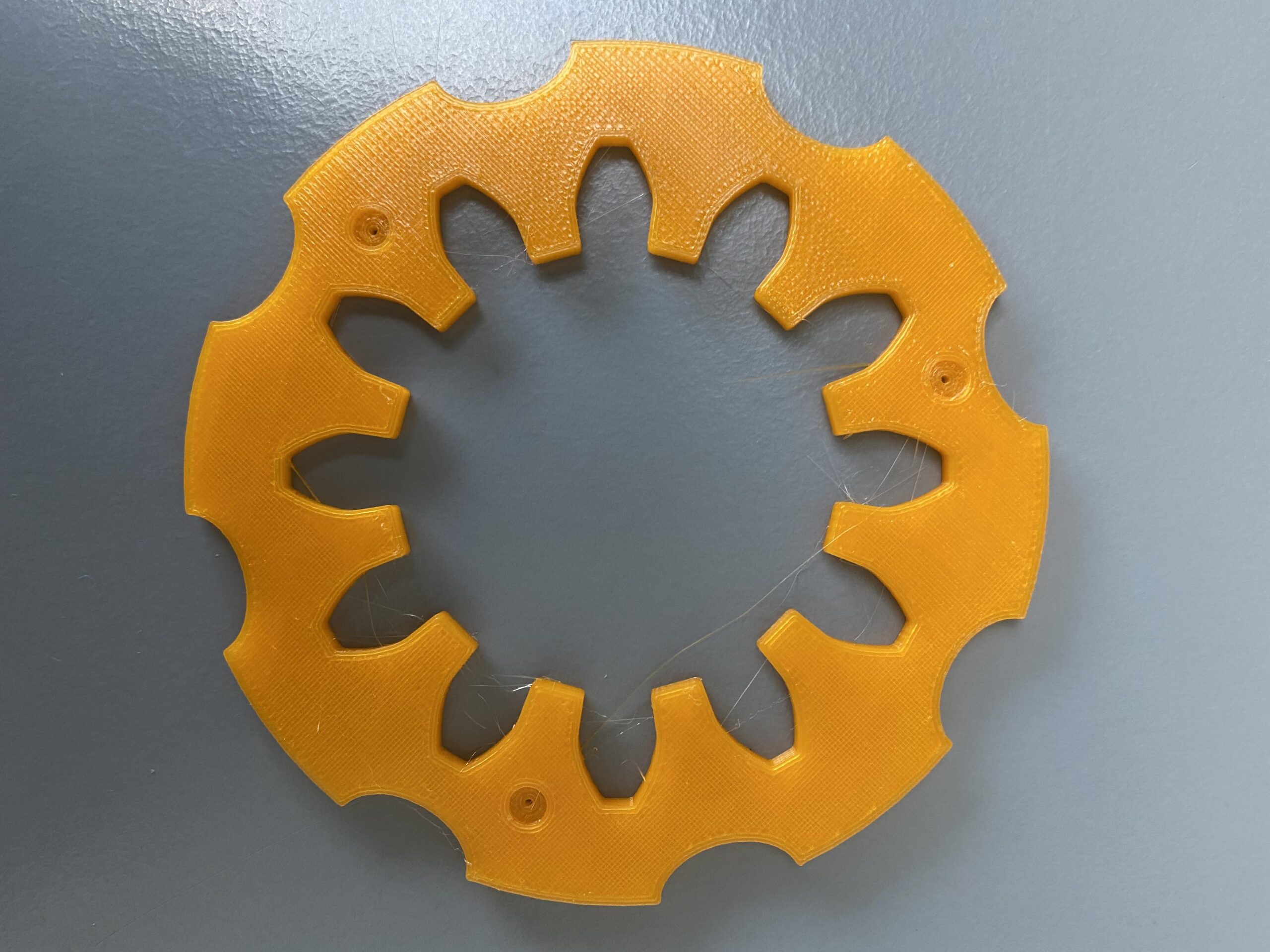
Photo: Spur wheel with 12 teeth (prototype 3D-print)
Detailed description of the spur wheel template
There are different types of spur wheels. This shape represents the mechanical properties with which the force can be maximised. When you interlink two wheels of this type, their teeth always have a point of contact under an angle of 90 degrees when rotating. Although it looks like an arbitrary number of teeth can be placed in a circle, this is not the case.
The wheels in the set have 12 or 15 teeth respectively. The spaces between them – their negative counterparts – are placed on the inside of the round template, so that the drawing result will have its teeth on the outside. The body of the spur wheel has finger fitters in eight positions along the outside for easy lifting or extra grip. You find pushpin markers in the top surface of the body.
Utilising the spur wheel template
The spur wheel is a relative complex tool to use / shape to create. We recommend to use one to two push pins to fixate to tool on the TactiPad. Draw the inner contour of the spur wheel and you have created the first step into the mechanical domain or flower design.
Once you have interlinked two spur wheels, you will experience a complex issue: finding the perfect position for one tooth on the one and two teeth on the other wheel to “bite each other”. This gives you an impression of how delicate spur wheel systems are in mechanics.
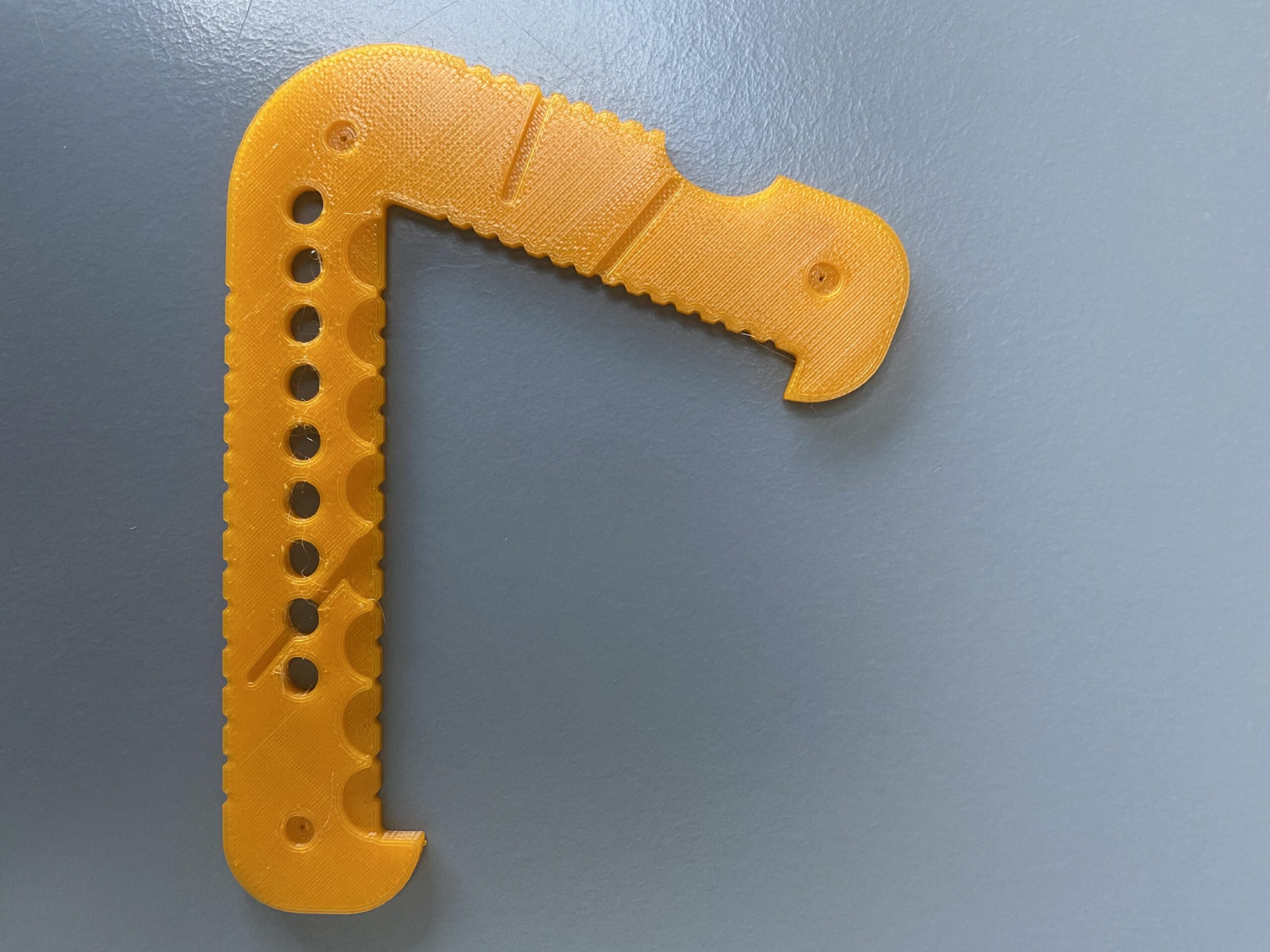
Detailed description of the regular polygon template
The set contains templates for regular polygons with five, six, seven, eight and nine corners referred to as pentagon, hexagon, heptagon, octagon and nonagon respectively. The radius of the polygons ranges from two to eight centimetres.
In a regular polygon all corners have the same angle. The corners are interconnected with lines that have all the same length. Another way to describe a polygon: A polygon consists of a number of equal leg triangles where the top corners of all equal legged triangles are at the same position. So they are arranged in a circle like slices of a pie. The distance from all corners to the centre point is the same.
The body of the tool is two centimetres wide. It is shaped as a triangle where one side is not present. It could be described as a jaw hook. The angle between the two sides is less than 90 degrees. Near to the rounded outside corner and near to the tips you find pushpin markers. One side of the polygon tool contains a number of wholes, indicating the number of corners of the particular polygon.
The side with the wholes is referred to as ‘radius side’. This radius side has a centimetre indication in the top surface and indents every half centimetre. The inner side of the side with the finger fitter to the far right is referred to as ‘drawing side’. The drawing side has the same number of indents as found on the radius side.
To construct the polygon, the pen position in the radius side has to correspond with the one in the drawing side, measured starting at the inner corner. As an example, a groove as a visual tactile clue ending at the four centimetre radius indication shows the direction to look for the corresponding indent in the drawing side and/or the respective bisectrix position. The value for the radius is measured starting at the inner sharp corner and increases towards the tip. The once selected position at the radius side is going to be the centre of the polygon.
At the outer side of the drawing side you find indents as well. They indicate the position for the bisectrix of the equal leg triangle. The outside corner in between the radius side and the drawing side is rounded to allow for alignment with the ruler; the distance from the sharp hook to the ruler remains the same when you move/rotate the polygon tool.
Utilising the regular polygon template
The regular polygon tools are mainly used to create these shapes. You can also create mandalas. You have to use at least one pushpin to mark the centre of the polygon. A second pushpin is handy to mark the position to draw to along the drawing side.
We use cookies to ensure that we give you the best experience on our website. If you continue to use this site we will assume that you are happy with it.