
In just a few weeks’ time, a new version of the TactileView software will be released. In this version we have introduced a number of new features that were requested by our users.
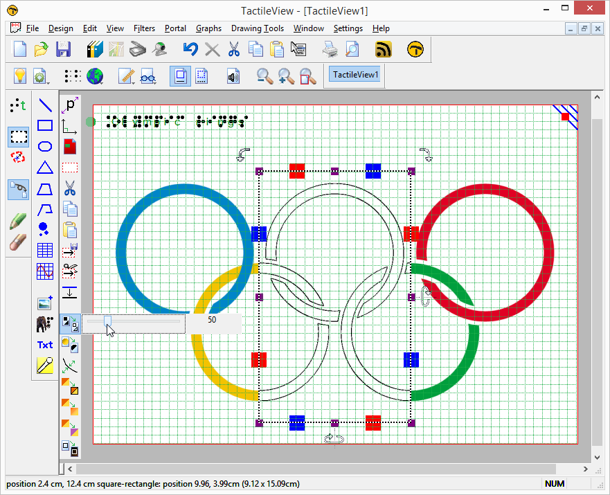
To give you a glimpse of what is to come, we would like to highlight two of the new software features in two short videos. The first one is the ‘dot view’. In this view mode, your designs will be shown in braille dots on screen, just as the document will appear on paper. In other words, what you see is what you feel!
Another important addition is the combination with the Duxbury Braille Translator (DBT). Their new release 11.3 and the new TactileView version 2.200 will allow you to easily create a single document with both text AND graphics in braille!
If you are attending the ATIA conference, held January 27-31 in Orlando, Florida, please visit the Irie-AT booth (nr. 209) for a personal try-out.
You are also kindly invited for Jeff Gardner’s presentation of TactileView, on Friday January 30 from 2.20 pm until 3.20 pm.

Photo: Screenshot of TactileView design in dot view