02 CircleFrame frame

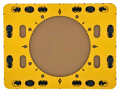
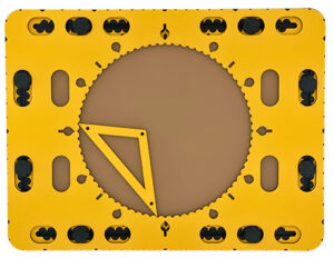
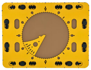
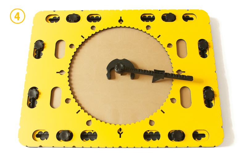
The circle frame of the CircleFrame toolset.
Photo: The circle frame of the CircleFrame toolset.

Global description of the circle frame

The actual frame of the CircleFrame has similar dimensions as the TactiPad (28 cm by 37 cm). The thickness of the frame is four millimetres. Near the outer edge of the frame oval holes can be found to place the frame in one of three positions on the TactiPad. For an a-centric position, two additional holes are present at both sides near the circle.

To description section
To manual section

Detailed description

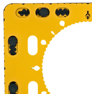
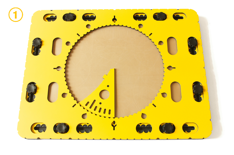
In the middle of the CircleFrame is a large circle cut out with a diameter of 20 centimetres. This is the actual drawing area. Along the edge of this circle medium sized indents every five degrees are provided, which form a large protractor. Around the outside of the circle there are extra markings: a teardrop shape for every 30 degrees, a line for every 45 degrees, or a combination of both where they coincide at 0, 90, 180 and 270 degrees. Indentations are placed around the outside of the circle frame in which rubber bands can be attached. These indentations are positioned at every 10 degrees seen from the centre of the circle. Slightly wider indents make the positions for 0, 30, 45, 60, 90 degrees, etc. easily recognizable

Circle frame manual

To description section

Storage of the CircleFrame

The frame of the CircleFrame will sit or can sit already on top of the drawing board for storage. The additional tools for the CircleFrame have their place in the paper pocket.

Preparing the drawing board

Place the knobs of the TactiPad five centimetres away from the corners. The CircleFrame can be placed n three different positions: in the middle of the drawing board with the edges coinciding with those of the TactiPad, or in two positions left and right of the drawing board’s centre when in landscape orientation. Make sure the eight oval holes near the outer edge of the CircleFrame fit all over a knob.

Because the circle is exactly in the middle of the circle frame, the frame is horizontally and vertically symmetrical. Mounting the CircleFrame on the TactiPad therefore needs no consideration.

Indications run along the edge of the circle indents for every 5 degrees, drop shaped ones every 30 degrees and straight ones every 45 degrees.
Photo: Indications run along the edge of the circle indents for every 5 degrees, drop shaped ones every 30 degrees and straight ones every 45 degrees.

Inserting the tools in the circle

The wedge tool, the 468triangle or the zigzag triangle can rotate freely over 360 degrees within the circle. The drawing tools preferably are aligned with the degree markings along the circle.

For detailed descriptions and manuals of related tools see:

03 Zigzag triangle
04 468Triangle
05 Wedge tool
06 More ideas

03 Zigzag triangle

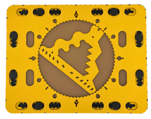
Zigzag triangle in the circle frame on the TactiPad.
Photo: Zigzag triangle in the circle frame on the TactiPad.

Global description

The size of the zigzag triangle is such so that it fits exactly inside the 20 centimetres diameter of the circle.The three sides of the body of the triangle all have a different pattern. The middle section of the triangle is open. The inner sides have the same patterns at a smaller scale as along the outside. The zigzag triangle is also called a ‘Christmas tree’.

To description section
To manual section

Detailed description

The corners of the triangle are rounded. One corner has an alignment indentation to align the triangle with the degree markings along the edge of the circle. The side opposite the indented corner is straight. Another one provides a smooth wave pattern, the final one has a zigzag pattern. Along the inner and outer side of the straight side two small indents indicate the length of a line segment to construct an hexagon. In the straight side oval holes can be found to hold a pen while rotating the triangle. The holes are placed to obtain curves at four, five, six, seven, eight or nine centimetres relative to the centre of the circle. Pushpin markers are placed near the corners.

Zigzag triangle manual

To description section

Preparing the TactiPad

Place all eight knobs of the TactiPad approximately five centimetres away from the corners. Place the circle frame on top of the TactiPad.

Using the zigzag triangle

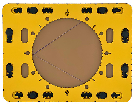
The zigzag triangle fits exactly inside the circle with the rounded corners nearly touching the circle edge. It can rotate freely. Place your pointing finger on the alignment indent and align the triangle at 12 o’clock. Now you can create an equilateral triangle inside the circle. Start with the indented corner at 12o’clock and draw along the straight outside of the triangle. Rotate the tool over 120 degrees clockwise (which is at 4 o’clock) and draw the line. Rotate once more over 120 degrees (which is at 8 o’clock).

Two sided of the equilateral triangle are drawn with the zigzag triangle.
Photo: Two sided of the equilateral triangle are drawn with the zigzag triangle.

Hexagon in the circle

Align the indented corner at any degree indication and draw a line only between the two indents along the inner or outer straight side. Rotate the triangle over 60 degrees and repeat the draw. In total four more rotations are required to finish the shape.

Hexagon is finished in the CircleFrame.
Photo: Hexagon is finished in the CircleFrame.

Repetitive patterns; Mandala type of figures

By tracing segments of the sides and/or combining patterns intriguing drawings will emerge. Whatever you do, the result is fascinating.

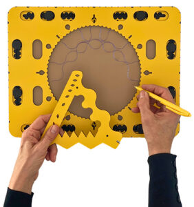
With wave-side of the zigzag triangle a repetitive pattern is made.
Photo: With wave-side of the zigzag triangle a repetitive pattern is made.

Oval holes to create arches

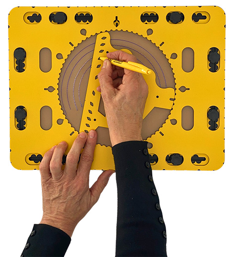
The holes in the straight side of the triangle can hold a pen. Rotate the triangle holding the pen. Arches with a length depending on the amount of rotation and the selected radius will occur.

Photo: Arches created by moving the zigzag triangle holding the pen in different holes.

04 468Triangle

The 468triangle in the circle frame on the TactiPad.
Photo: The 468triangle in the circle frame on the TactiPad.

Global description

The 468triangle is an open triangular shaped frame with a width of one centimetre. The number 468 refers to the steps required for the triangle to return on the exact same position in the circle; four, six or eight steps respectively. Beyond this it serves as a template for ‘home made’ templates.

To description section
To manual section

Detailed description

The corners of the triangle are pointy so they fit in the indents at the edge of the circle of the framework. The length of the sides are designed so they exactly span an arc of 45, 60 or 90 degrees, seen from the centre of the circle. Pushpin markers are located at the top surface.

468Triangle manual

To description section

Square, hexagon and octagon

The 468triangle can have its starting position anywhere in the circle. Tracing along the longest inner side of the triangle results in a square. Tracing the shortest side gives an octagon. The third one an Hexagon.

Home made templates

The 468triangle can serve as an example to create your own drawing templates out of cardboard or an other sturdy material. By giving one side of the template a length similar to one of the triangle sides, it will fit by rotating eight, six or four times in the full 360 degrees of the CircleFrame.

Your template

Cut out an irregular shape from the centre of your template. Place the template against the edge of the circle and trace the inner contour. Depending on the chosen length, rotate the template 45, 60 or 90 degrees to obtain a symmetrical pattern. Recurrence and/or partial overlap will give your drawing an unexpected appeal.

05 Wedge tool

Wedge tool to draw pie charts,
Photo: Wedge tool to draw pie charts.

Detailed description

The wedge-shaped drawing tool has a rounded edge that matches the curve of the circle in the CircleFrame. This rounded side covers an arc of 45 degrees. Near the rounded edge grooves per six degrees (one minute) are located. A little further away from the edge a hole is present. Two sides of this tool end in a flattened point. One of these sides is straight and ends in a very small point that serves as a pen blocker. This pen blocker also exactly coincides with the centre of the circle. The straight side forms the radius for the circle. The other side of the wedge is slightly curved inward. This side has small indents at every centimetre. The small block between the indents at 2 and 3 centimetre is used to position the compass base.

To description section
To manual section

Wedge tool manual

To description section

Make sure the CircleFrame is placed properly on the TactiPad.

Drawing pie charts

The wedge tool can be used to draw pie charts, which are often used to present statistic information in fields such as mathematics, economics and geography. The quantity that each sector represents corresponds with an arc of a certain number of degrees. By determining the angle between two radii on the inside of the circle, you can draw the pie chart very accurately. Keep the tool in place with one or two fingers in the hole in the tool and press it against the edge of the circle.

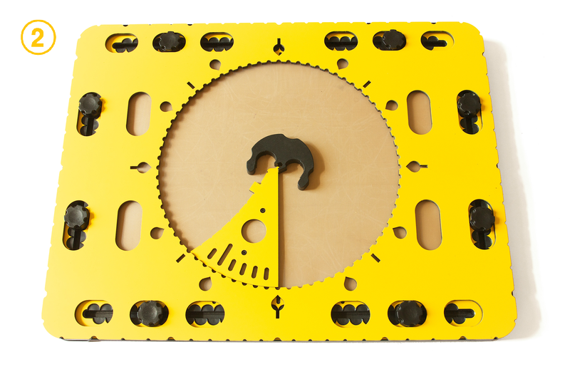
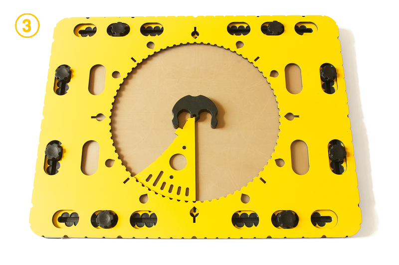
 Many other mathematical concepts in which degrees and angles play a key role, such as vectors or polar and trigonometric functions, can be explained and drawn as well using the CircleFrame. Centring the compasses in the CircleFrame. Another function of the wedge tool is to position the compass in the centre of the CircleFrame. You can achieve this by placing the wedge tool anywhere against the edge of the circle with the compass base against the flattened tip of the wedge. The centre of the compass base now hooks around the pen blocker at the tip of the wedge tool.

By slightly turning the base counter clockwise, it will catch the small protruding block on the curved side of the wedge. This way, the compass base is exactly in the middle of the circle. By removing the wedge tool and placing the compass arm into the base, you can draw a circle precisely in the centre of the CircleFrame.

Figure 2. Position the wedge tool along the edge of the circle (step 1), position the compass base and turn it so it rests against the wedge tool (steps 2 and 3) and remove the wedge tool (step 4). The compass is now perfectly positioned in the centre.

Drawing the hands of a clock

Around the circle of the CircleFrame, multiples of 30 degrees are indicated by drop-shaped indentations. These make up for the twelve hours of the clock. To draw a clock hand, you can use the wedge tool. Along the rounded side you will find grooves at an angle corresponding to 1 minute, or 6 degrees. The longer groove of 2 centimetre indicates the position of 5 minutes or 1 hour later. After placing the wedge tool with the rounded side against the edge of the circle and aligning the straight side with one of the hour indications, you can set the minute and draw the hands of the clock as radii and have it set at any desired time.

06 More ideas

Rubber bands spanning the diameter

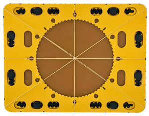
Indentations are placed around the outside of the circle frame in which rubber bands can be attached. These indentations are positioned at every 10 degrees seen from the centre of the circle. Slightly wider indents make the positions for 0, 30, 45, 60, 90 degrees, etc. easily recognizable. When spanning to opposing indentations with a rubber band, they meet the centre, forming also the diameter of the circle.
It also exactly coincides with the degree indications along the circle’s edge.

Rubber bands running across the circle frame.
Photo: Rubber bands running across the circle frame.

Compass: circles in a circle

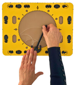
You can also combine the compass with the edge of the circle. The indents per five degrees are semi-circular and have the same diameter as the needle of the compass. Place the compass foot partly on the edge so the needle of the compass fits in an indentation of the CircleFrame. Set the desired radius for the circle to be drawn. The set radius for the circle determines the length of the curve that can be created. The centre of the arcs are now exactly on the edge of the frame. By drawing multiple arcs along the edge of the circle, you can create intriguing repetitive geometric patterns.

The compass foot on the edge of the circle frame. Repetitive arcs are drawn.
Photo: The compass foot on the edge of the circle frame. Repetitive arcs are drawn.

Fantasy

As an example set the radius at 10 centimetres. Place the compass base at 12 o’clock and draw the maximum possible curve. Place the base at 3, 6 and 9 o’clock respectively and create the curves as well. Trace the circle’s contour and remove the circle frame. The curves will cross in the middle of the circle.

0.5 GraphGrid frame

The GraphGrid frame

Detailed description
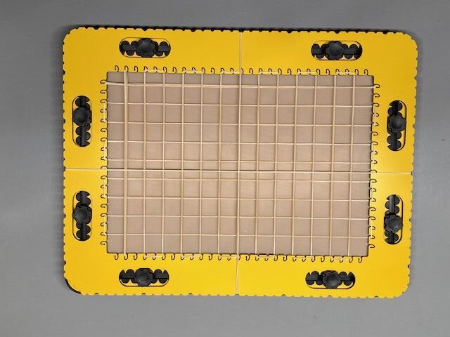
The GraphGrid frame is yellow with a thickness of four milimetres. It is placed on the TactiPad like a picture frame. Eight oval holes in the frame fit around the knobs of the TactiPad to hold it in place. Three of the four corners are rounded.
Along the inner edge, small curved hooks are placed at a regular interval of 1 centimeter. Along the outer edge of the GraphGrid, indentations are made with a spacing of 1 centimeter as well. Slightly wider indications mark 5 centimeter intervals. The indentations hold rubber bands.
The locations of the hooks and indentations both exactly match with the centimetre scale along the edges of the TactiPad.
The ‘graphing paper’
The measurements of the drawing board become tangible on the entire drawing surface.
The frame overlaps the drawing surface along the edges by one centimeter.
Because of the A4 dimensions of the drawing surface (29.7 cm by 21.0 cm), the centimeter scale is not symmetrical along the TactiPad. Therefore the starting point for horizontal and vertical distances is at the upper left corner of the drawing board and GraphGrid frame when in landscape orientation.

0.4 Hyperbole tool

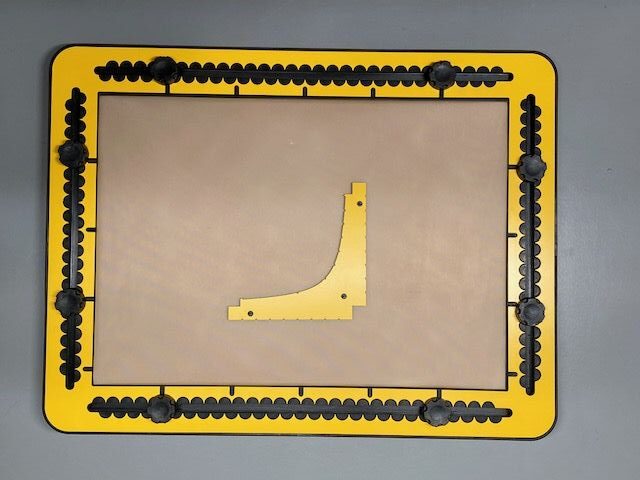
Hyperbole; tool to draw y=1/X

Global description
The global shape of the tool is a rectangle hook with the curved contour at the inner side.
Pushpin markers are provided at the top surface.
A small square for alignment is left out at the lower left corner of the tool.
By nature of the formula, the tails of the tool become very thin. To maintain the sturdiness of the tool, additional material has been added.
the graph contour endings contain a pen blocker.

Detailed description
The formula represented in this tool is a smooth curve only going down, seen from
X equals 0 to X equals 8.
Along the curve small indents are provided to indicate Y values corresponding with X values equal 0,25, 0,50, 1, 2, 3, 4, 5, 6, 7 and 8 respectively.

0.3 Lens tool

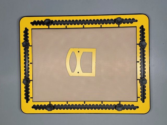
Lens; tool for convex and concave lens or mirror

Global description
The symmetrical tool could be described as a traditional house where the top part is curved. The first floor is one big window where to top side is curved. The second floor has a window where the top and bottom sides are curved in opposite directions.
The shape of all curves represent the curves of the lenses.
In the top and bottom sides of the tool small indents are provided to align the tool on the median light beam.
Pushpin markers are provided at the top surface.

0.2 Parabola tool

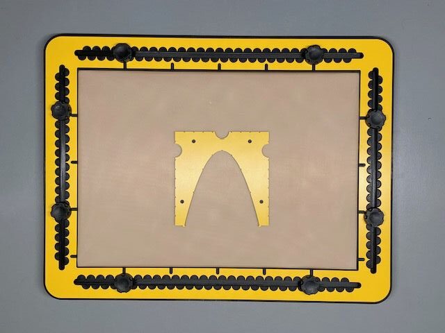
Parabola; X to the power of 2

Detailed description
The inner space of this U-shaped tool has the contour of the formula X to the power of two.
The two poles of the U have indented centimetre indications along the outside.
Three medium size alignment indents are provided near the bottom; one in the middle and one in each of the two poles.
Pushpin markers are provided in the top surface of the tool.
The contour of the graph goes down and up again. At the two ends of the contour pen blockers are provided.
Indented positions along the curve reflect Y values for X equals -2, -1, -0,5, 0, 0,5, 1 and 2.

0.1 SinTang tool

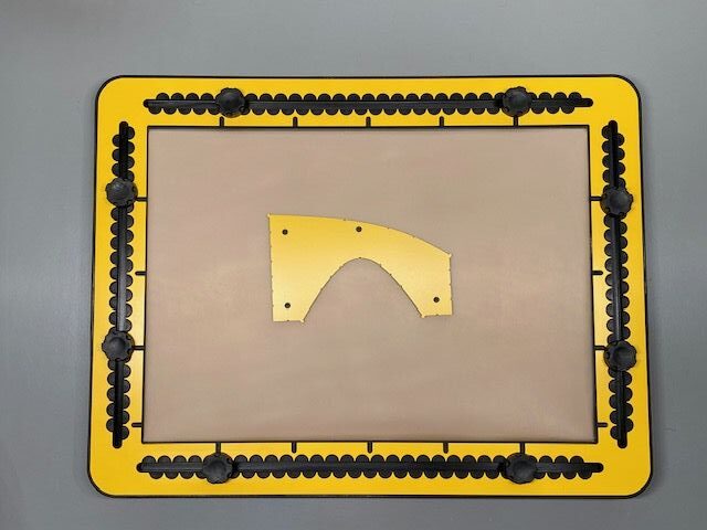
SinTang; combination tool for the sine, cosine and tangent graph

Global description
The SinTang tool combines graphs for two formulas; the sin(X) and the tan(X). More precise, a half period of the sine graph and a quarter of the tangent graph.
The sine graph, is the ‘hill’ contour which is the first half period of the sine graph. The cosine is a to the left shifted sine graph.
When placing the tool looking at the hill, the top side of the tool is a left to right downhill slope. After rotating 90 degrees clockwise it represents a quarter of the tangent graph.
The vertical left and right hand sides have an indented centimetre indication.
Pushpin markers are provided at the top surface.
For sine and tangent values of 1, the distance along the Y-axis is 4 centimeters. These dimensions provide sufficient ‘tactile space’.

Detailed description of the sine tool
The range from 0 to 180 degrees X values is distributed over a length of eight centimetres (aprox. 3 inches).
At 90 degrees is the top of the graph (maximum amplitude) at an height of four centimetres.
Small indents are provided in the curve at 30, 45, 60, 90, 120, 135, 150 degrees positions.
Pen blockers are provided at 0 and 180 degrees positions.

Detailed description of the tangent tool
To use the tangent part of the tool it has to be rotated for 90 degrees clockwise.
The contour of the tangent has small indents indicating the 30, 45 and 60 degrees positions on the X axis. The tan(45) is 1. The value of the graph is 4 cntimetres.
Pen blockers are provided at the 0 degrees and towards the 90 degrees position.
A length of four centimetres along the X axis covers a range of 90 degrees.

Item added to cart.
0 items - $0.00