Skip NavigationMenu

04. Polygon Tool

Detailed description of the polygon tool

The TactiForma set contains tools to create regular polygon shapes with five, six, seven, eight or nine corners referred to as pentagon, hexagon, heptagon, octagon and nonagon respectively.
The radius of the polygons range from three to eight centimetres.
The magnetic foot is an essential part of the regular polygon tool, to hold the tool in place.

Foreword
The regular polygon shape and the regular polygon tool itself need some more explanation than other TactiForma tools for a good understanding. Especially the regular polygon section in the design story of the TactiForma provides more background about the design requirements.
In order to use the regular polygon tool, using pushpins is recommended.

The regular polygon shape based on triangles
A regular polygon is a shape where the individual sides are all of the same length.
It can also be described as a circle filled up with isosceles triangles. The sides of two adjacent triangles co-inside. The sides of the triangles are not present in the drawing. Only the base sides are visible as the sides of the polygon shape.
For later on: Each triangle of the regular polygon is called a segment.

Global description of the tool
To understand the setup of the tool, imagine a line drawing of an isosceles triangle pointing upwards. The base side is horizontal. The top corner is above the middle of the base side. The angles for the respective top corners of the pentagon, hexagon, heptagon, octagon and nonagon are 72, 60, 51, 45, and 40 degrees.
The top of the triangle is going to be the centre of the polygon. The tool is rotating around this centre point while shifting from one segment on to the next.
The two sides of the triangle are in fact the rulers to measure and set the radius of the polygon.

Body of the tool
Keep the triangle from above in mind. The equal sides of the triangle are rulers, the legs of the tool. An important detail; the right ruler goes along the outside of the triangle, the left ruler along the inner side of the triangle. In effect the rulers are placed asymmetric. This comes in handy when drawing. See drawing instructions.
Both rulers would meet in the top corner, but a top section of the triangle is cut off and replaced with a ring, so the rulers are only partly present.
The hole in the ring leaves space to find the centre position of the polygon and is also the fit for the magnetic foot to hold the tool in place during the rotation of the tool.

Tactile properties
The legs have a centimetre indication at the top surface and along the side indents at every half centimetre. At the outer side of the right leg, medium sized indents are provided to indicate the type of polygon. E.g. six indents means the hexagon polygon tool.
Seen from the centre point, the ruler goes from three to eight centimetres.
Each ruler has a pushpin marker near to the ring and at the end.
The ring has an inner radius of nearly two centimetres and an outer radius of nearly three centimetres. Three small indents are at the outside of the ring.
One of them is placed on the line formed by the bisector. Two others on an orthogonal line that crosses the centre position.
The round foot has two magnets fully encapsulated in rubber, to hold the body of the tool in place. It is lacking a section so the fingertip can slide in. This open area is called finger entrance. It enables exploring the drawing near the polygons centre area.
The vertical groove in the middle of the finger entrance indicates the precise centre position of the polygon. The groove can partly surround a pushpin.

For more information, have a look at the Polygon Tool Manual page.

03. Rectangular Hook Tool

Detailed description of the rectangular hook tool

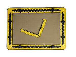
The rectangular hook tool has the shape of a capital l, where the horizontal and vertical part of the character have the same length of 10 centimetres / approx. 4 inches.
The two parts enclose an angle of 90 degrees. They are equipped as a ruler with measurement indications in centimetres at the top surface and indents per half centimetre along the sides.
The body of the tool is two centimetres wide. On the outer side, near to the rounded corner and to the tips you find finger fitters for easy lifting or extra grip.
The corner between the sides is rounded at the outer side. At the top surface is a groove under an angle of 45 degrees for alignment.
The rulers are ending with a 90 degree hook serving as a pen blocker.
Pushpin markers are located near the rounded corner and near to the tips.

For more information, have a look at the Rectangular Hook Tool Manual page.

02. Triangle Tool

Detailed description of the triangle tool

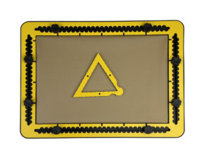
The length of the sides range from three to nine centimetres. The body of the triangle is about 12 millimetres wide. On all three of the outer sides a finger fitter is provided for easy lifting or extra grip. One outer corner is rounded, the other two are sharp. All three corners have a pushpin marker at the top surface.
Along the outside and inside are indents located at every centimetre. They align with each other. In case the length of the side is odd numbered, there is an indent in addition at the halfway position.

For more information, have a look at the Triangle Tool Manual page.

01. Square Tool

Detailed description of the square tool

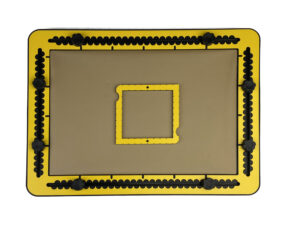
The sizes of the squares ranges from two to eight centimetres. The frame that forms the square is one centimetre wide.
Two finger fitters are provided in opposing sides. Two opposite diagonal corners are rounded. The others are sharp. At each corner a pushpin marker is located.
Along the outside and inside a small indent is provided at every centimetre.
In case the length of the side is odd numbered, there is in addition an indent at the halfway position.

For more information, have a look at the Square Tool Manual page.

Sharing tactile emojis

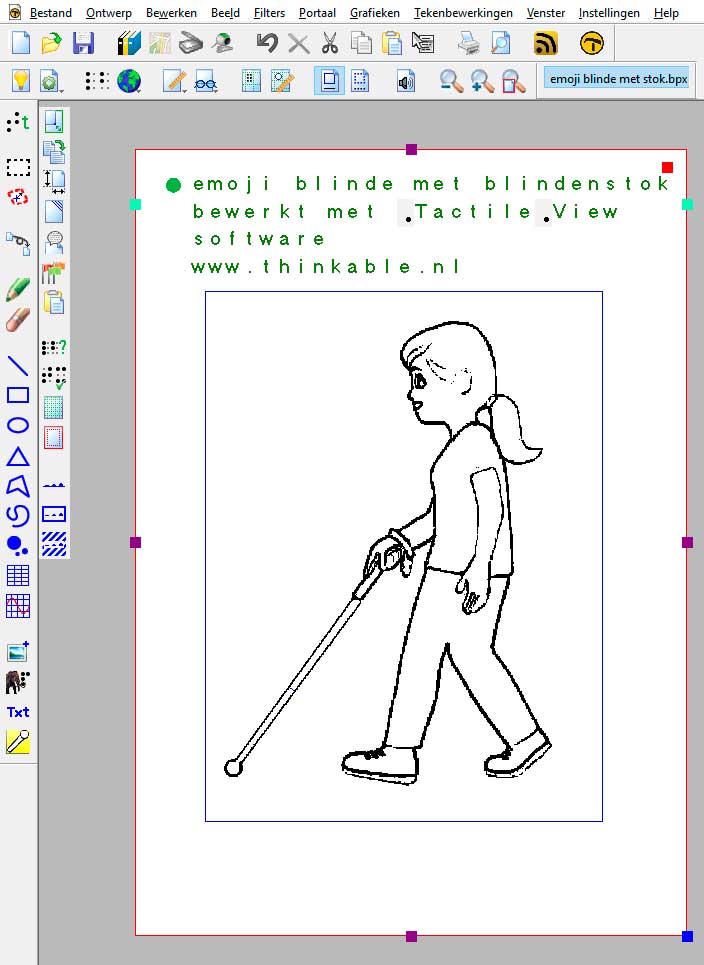
As we mentioned in a previous newsletter, we created a few of the newly suggested emojis as tactile diagrams for our visitors of the 2019 ZieZo exhibition. They were very well received. We are happy to share the four designs with you. You can download the designs here.

Please keep in mind that the images were created with TactileView and saved in .BPX format. In order to take full advantage of the tactile graphics you need a registered version of the software; printing them using the demo version will add some watermarks.

Emoji of blind person with cane

MDA initial idea

MDA initial idea generation

When we recently came across the first prototype of the compasses for the TactiPad, it got us thinking: what if we could motorise it? What if we used a motorised drawing arm to combine the best aspects of both the TactiPad drawing board and TactileView graphics software?

Read moreMDA initial idea

Theo’s challenge for the MDA

Theo and Jaap drawing a school logo with the MDA

I was looking forward to finding out what progress had been made on the motorized drawing arm since I saw the prototype at Sight village last year.
I heard that it could draw out pictures so I planned a test for it. First I downloaded a copy of my school logo (png file) onto my phone before Sight Village (2019).

Read moreTheo’s challenge for the MDA

Pass your upcoming math exams with the MDA

Graph sketched on the TactiPad by the MDA

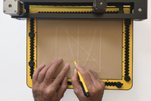
The motorised drawing arm (MDA) is capable of sketching a wide variety of designs, created with the TactileView software, right onto the TactiPad drawing board. We will be demonstrating the full setup of our system at the SightCity exhibition in Frankfurt. We will show you how a student can use it to pass the upcoming math exams, or how a teacher can use our system to prepare math assignments. Of course, a great variety of different subjects can also be sketched…

Read morePass your upcoming math exams with the MDA

Two MDAs pre-ordered; are you next?

The moment has finally come: after a busy development period, we are proud to announce that the Motorised Drawing Arm (MDA) is now available for pre-order!

For us, it has been a very inspiring period since we first showed you this product idea. The MDA has certainly attracted a lot of attention so far!

The outcome of the development is a unique product to create tactile diagrams in a brand new way.
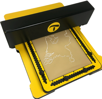
In short, a design from the TactileView sofware is sketched on the TactiPad drawing board by a motorised stylus, creating a reased line drawing.

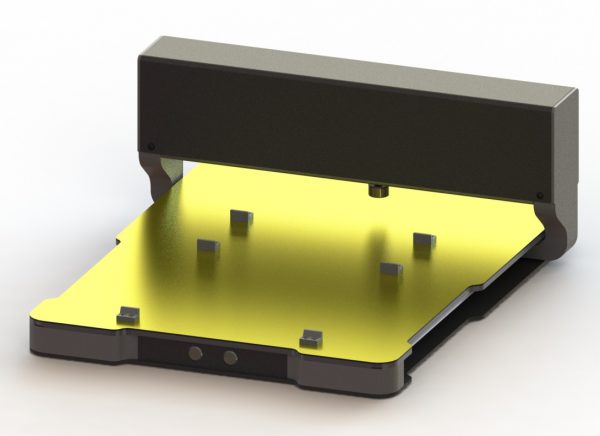
Computer rendered image of the first production model of the MDA

New interactive applications
By combining accurate digital tactile graphics with the ability to expand these by hand, the MDA opens up a wide range of new interactive applications for students, teachers and professionals. Designs can be quickly reproduced for multiple users, for example several students in a classroom.

On our restyled Thinkable website, you can find all details about the use of the MDA or the different applications we have in mind.

MDA Smart Module
The MDA can also be extended with the Smart Module. Instead of connecting the MDA with USB to your computer, this Smart Module will enable you to wirelessly sketch a design on the MDA. You can even operate the sketching process via the browser on your smart phone or tablet!

Pre-order your MDA (and get a bonus)
We are currently preparing to first production run for the MDA, with an expected delivery date of June 30th 2018. You are invited to place your pre-order to be one of the very first people to start using the MDA. Better still, all pre-orders will receive the MDA Smart Module for free!

If instead you are interested in ordering the MDA at a later stage, we would also be very grateful if you could already let us know that you are interested. You can simply use our order page to notify us.

Experience the MDA at the ZieZo, CSUN and SightCity exhibitions
We have three exhibitions scheduled at which you can explore the possibilities of the MDA:

– March 16th and 17th at the ZieZo exhibition in Utrecht, the Netherlands;
– March 21st to 23rd at the CSUN Assistive Technology conference in San Diego, California. You can find us in the Irie-AT booth, nr 605;
– April 25th to 27th at the SightCity exhibition in Frankfurt, Germany.

Our open, transparent prototype will allow you to see all the inner workings behind the MDA’s drawing mechanism up close, while a computer generated render will show you the looks of the production model.