Skip NavigationMenu

TactileView – Sight City = Sight Seeing

On coming Wednesday may 23th the annual exhibition Sight City is opening its doors again.

The exhibition takes place in Frankfurt Flughafen in the Sheraton hotel. The ‘city’ is really full of booths where you can find a wide variety of products and services that have something to do with ‘sight’. ‘Seeing’ them all in one day is nearly impossible, but if you would just see the half of them, your ‘sight’ could be cleared.

Jaap Breider will give a speech on Wednesday from 12:15 to 12:45 in the forum about the challenges that are encountered in the process of creating tactile diagrams.

TactileView will be present during the 3 days in booth H11. We will demonstrate the TactileView software, the TactiPad drawing board, the TactileView ClickPad and the first version of the TactileScope.

When you make it to Frankfurt, please visit us in booth H11.

In case you are not able to come by, we sent you the brochure that we have prepared.

The brochure we hand out is as article available at TactileView – A wealth of tactile images for a visual impaired person

To indicate where you have to go in this huge facility, see our location on the map at www.sightcity.net

Parabola symbolising the year’s end

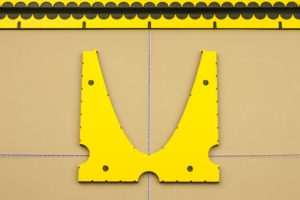
The new parabola tool for the GraphGrid

New parabola tool on the TactiPad

With the end of the year fast approaching, we hope you can look forward to enjoying the holiday season.

For us, the end of the year resembles the curve of a parabola. Things will gradually slow down for a well-earned rest, until midnight on the 31st of December when everyone is holding their breath to welcome 2017. In the new year, everything will be picking up speed once more with renewed enthusiasm.

Plans for 2017

We are pleased to let you know that the GraphGrid accessory set for the TactiPad has been extended with three additional tools. These allow you to draw perfect parabolas, hyperbolas and concave or convex lenses.

But more on that later – for now, we want to wish you a merry Christmas and the happiest of New Years!

ATIA conference; hands-on demonstration of the new release

Thinkable products at the ATIA conference

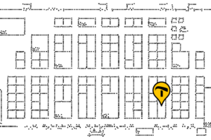
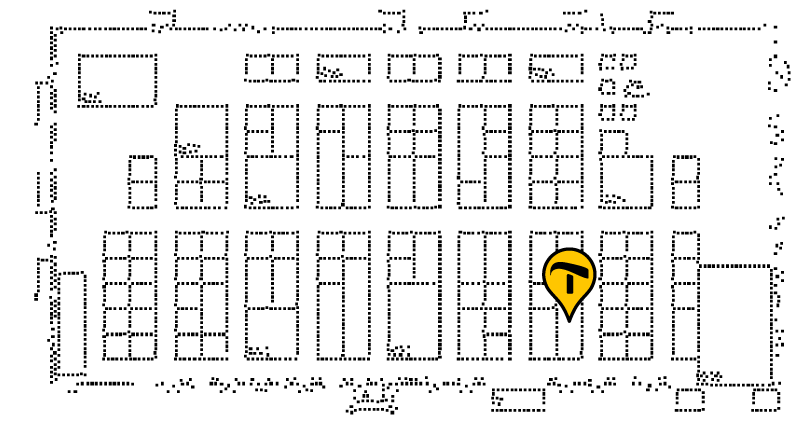
Tactile floorplan of the ATIA conference, with Irie-AT's booth marked

With the new year in full swing, the first in the list of global assistive technology conferences of 2017 is about to start. Visit the ATIA in Orlando, Florida on January 18-20 to get a hands-on demonstration of the TactiPad drawing board and TactileView tactile graphics software.

In booth 800, Irie-AT will be happy to demonstrate the reasons why both TactileView and the TactiPad are met with ever increasing enthusiasm by visually impaired users and professionals alike.

Additions and improvements in TactileView version 2.500

Hopefully you can enjoy some of the winter sun in Florida. Meanwhile, we will continue to work hard on putting the finishing touches to TactileView version 2.500 for you to download once you have returned home. To discover the changes and improvements, you can already check the release notes and what’s new page on our website.

01. GraphGrid – Shape and function

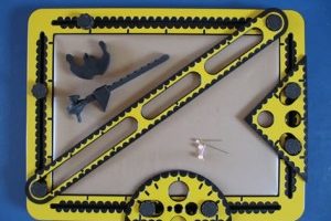
The GraphGrid is one of the smart accessories for the TactiPad drawing board. Besides drawing freehand this accessory allows you to draw rows, columns, squares or a coordinate system in two or three dimensions. Rubber bands fixed inside and around the GraphGrid allow you to place flexible ‘graph paper’ and ‘coordinate systems’ on the TactiPad. When making creative drawings, playing games or doing school assignments, this allows you to work easily with cross-connections in tables, differences between fore- and background or spatial proportions.
The GraphiGrid placed on the TactiPad

Figure 1. The GraphGrid is placed on the TactiPad’s buttons.

Details of the GraphGrid

The GraphGrid is a framework that is placed on the TactiPad like a picture frame. Rubber bands, placed inside and around this framework from left to right and from top to bottom, form the axes and lines of the graph paper.

Along the inner edge, small “hooks” are placed at a regular interval of 1 centimeter. Along the outer edge of the GraphGrid, indentations are made with a spacing of 1 centimeter as well. Slightly wider indications mark 5 centimeter intervals. The locations of the hooks and indentations both exactly match with the centimeter scale along the edges of the TactiPad. This way the measurements of the drawing board become tangible on the entire drawing surface. The frame overlaps the drawing surface along the edges by one centimeter.

Because of the A4 dimensions of the drawing surface (21.0 by 29.7 cm), the centimeter scale is not symmetrical along the TactiPad. Therefore the starting point for horizontal and vertical distances is at the upper left corner of the drawing board, when it is in landscape orientation with the hinge facing backwards. To position the GraphGrid in its correct position, place it with the flat corner in the upper right corner on the TactiPad.

The eight holes in the GraphGrid fit around the knobs on the TactiPad. For this, you place the knobs at five centimeters from the corners of the drawing surface.

02. Circle frame

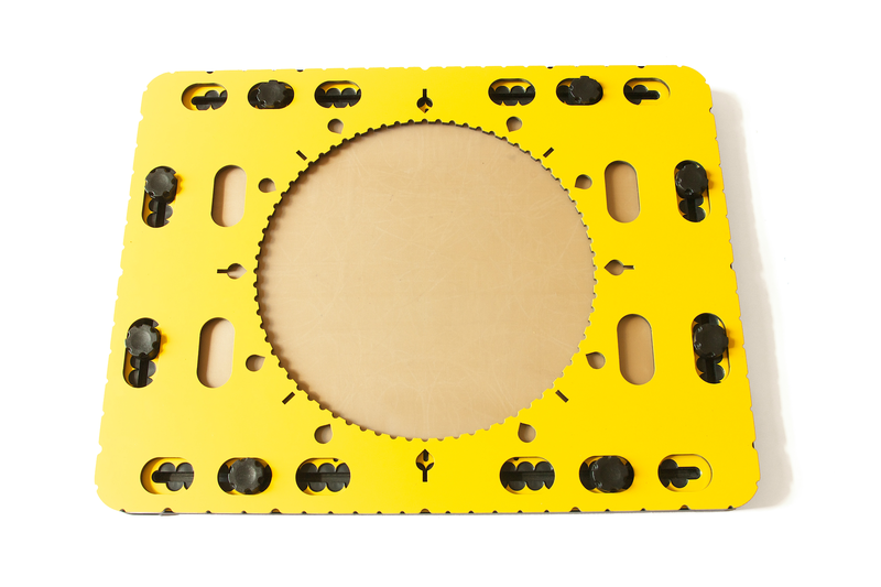
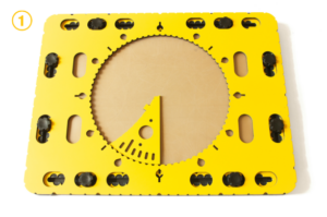
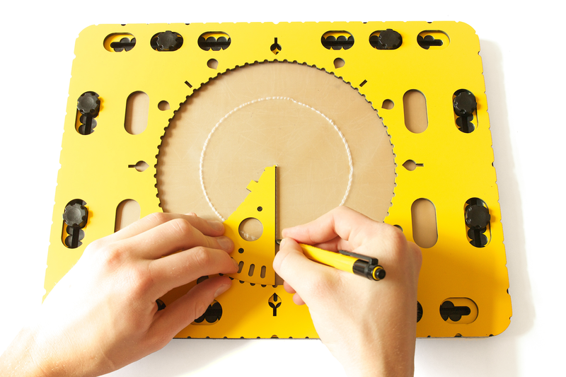
The CircleFrame is the name of the product which includes the wedge tool, the 468 triangle and the zigzag triangle, and a frame with a large circle in the middle. The frame itself is called circle frame (no capitals).

Circle frame on the TactiPad

Photo: Circle frame positioned on the knobs of the TactiPad.

Detailed description of the circle frame

The circle frame has similar dimensions as the TactiPad (28 cm by 37 cm). The thickness of the frame is four millimetres.
Near the outer edge of the frame oval holes can be found to place the frame in one of three positions on the TactiPad.
For an a-centric position, two additional holes are present at both sides near the circle.
In the middle of the circle frame is a large circle cut out with a diameter of 20 centimetres. This is the actual drawing area for the drawings.
Along the edge of this circle clear tactile markings every five degrees are provided, which form a large protractor.
Around the outside of the circle there are extra markings: a teardrop shape for every 30 degrees, a line for every 45 degrees,
or a combination of both where they coincide at 0, 90, 180 and 270 degrees.
Indentations are placed around the outside of the circle frame in which rubber bands can be attached.
These indentations are positioned at every 10 degrees seen from the centre of the circle.
Slightly wider indents make the positions for 0, 30, 45, 60, 90 degrees, etc. easily recognizable

Circle frame manual

Because the circle is exactly in the middle of the circle frame, the frame is horizontally and vertically symmetrical. Therefore, there is no difference in shape between the yellow and black side. The orientation of the circle frame on the TactiPad therefore needs no consideration.

Preparing the TactiPad
Place the knobs of the TactiPad five centimetres away from the corners.
The circle frame can be placed in three different positions: in the middle of the drawing board with the edges coinciding with those of the TactiPad, or in two positions left and right of the centre when in landscape orientation.
Make sure the eight oval holes near the outer edge of the circle frame fit all over a knob.

Circle frame on the TactiPad

Photo: Indications run along the edge of the circle: small indents for every 5 degrees, drop shaped ones every 30 degrees and straight ones every 45 degrees.

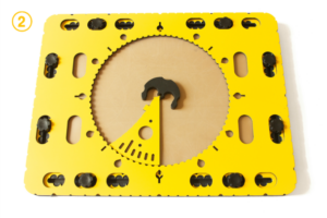
Insert the tools in the circle
The wedge tool, your templates based on the 468triangle or the zigzag triangle can rotate freely over 360 degrees within the circle.
The drawing tools preferably are aligned with the degree markings along the circle.

For detailed descriptions and manuals of related tools see:

Zigzag triangle

468Triangle

Wedge tool

More ideas

03. Zigzag triangle

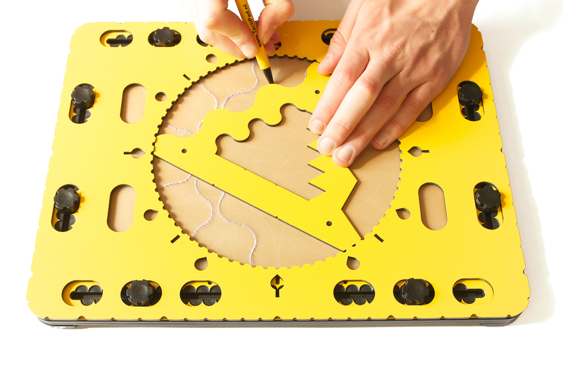
Photo: Zigzag triangle in the circle frame

The size of the zigzag triangle is such so that it fits exactly inside the 20 centimetres diameter of the circle.
The three sides of the body of the triangle all have a different pattern. The middle section of the triangle is open.
The inner sides do have the same patterns as the outside, at a smaller scale.
The zigzag triangle is also called a ‘Christmas tree’.

Detailed description

The corners of the triangle are rounded. One corner has an alignment indentation to align the triangle
with the degree markings along the edge of the circle. The side opposite the indented corner is straight.
Another one provides a smooth wave pattern, the final one has a zigzag pattern.
Along the inner and outer side of the straight side two small indents indicate the length of a line segment to construct a hexagon.
In the straight side oval holes can be found to hold a pen while rotating the triangle.
The holes are placed to obtain curves at four, five, six, seven, eight or nine centimetres relative to the centre of the circle.
Pushpin markers are placed near the corners.

Zigzag triangle manual

Preparing the TactiPad

Place all eight knobs of the TactiPad approximately five centimetres away from the corners. Place the circle frame on top of the TactiPad.

Using the zigzag triangle

The large zigzag triangle fits exactly inside the circle with the rounded corners nearly touching the circle edge. It can rotate freely.
Place your pointing finger on the alignment indent and align the triangle at 12 o’clock.

Equilateral triangle inside the circle

Start with the indented corner at 12 o’clock and draw along the straight outside of the triangle. Rotate the tool over 120 degrees clockwise (which is at 4 o’clock) and draw the line.
Rotate once more over 120 degrees (which is at 8 o’clock).

Hexagon in the circle

Align the indented corner at any degree indication and draw a line only between the two indents along the inner or outer straight side. Rotate the triangle over 60 degrees and repeat the draw.
In total four more rotations are required to finish the shape.

Repetitive patterns; Mandala type of figures
By tracing segments of the sides and/or combining patterns intriguing drawings will emerge. Whatever you do, the result is fascinating.

Zigzag triangle is used to draw intriguing shapes and repeating patterns

Photo: With the zigzag triangle you can create intriguing shapes and patterns.

Oval holes to create arches
The holes in the straight side of the triangle can hold a pen.
Rotate the triangle holding the pen.
Arches with a length depending on the amount of rotation and the selected radius will occur.

For detailed descriptions and manuals of related tools see:

Circle frame

468Triangle

Wedge tool

More ideas

04. 468Triangle

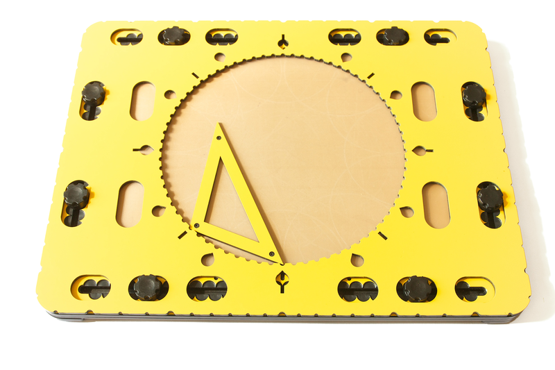
The small triangle tool is placed along the edge of the circle

Photo: 468Triangle

Detailed description

The 468Triangle is a triangular shaped frame with a width of one centimetre.
The main purpose is to serve as a template for ‘home made’ templates.
The inner space of the triangle is open.
The corners of the triangle are pointy so they fit in the indents at the edge of the circle of the framework.
The length of the sides are designed so they exactly span an arc of 45, 60 or 90 degrees, seen from the centre of the circle.
The ‘468’ refers to the number of rotations required for the triangle to return on the same position in the circle; four, six or eight times.
Pushpin markers are located at the top surface.

468Triangle Manual

The 468Triangle tool is intended to create your own drawing templates out of cardboard or other sturdy material.
Giving one side of the template a length similar to one of the triangle sides, it will fit by rotating eight, six or four times in the full 360 degrees of the CircleFrame.

Your template
Cut out an – irregular – shape from the centre of your template.
Place the template against the edge of the circle and trace the inner contour.
Depending on the chosen length, rotate the template 45, 60 or 90 degrees to obtain a symmetrical pattern.
Recurrence and/or partial overlap will give your drawing an unexpected appeal.

Alignment with indents from start to end

Because the side of your template has a specific length, it will by rotating the template eight, six or four times respectively, along the circle’s edge, end up at the starting position again.

The 468Triangle tool is placed along the edge of the circle

Photo: The 468Triangle tool is placed along the edge of the circle in the frame

05. Wedge tool

Creating a pie chart with the wedge shaped tool

Photo: Wedge tool

Detailed description

The wedge-shaped drawing tool has a rounded edge that matches the curve of the circle in the circle frame. This rounded side covers an arc of 45 degrees. Near the rounded edge grooves per six degrees (one minute) are located. A little further away from the edge a hole is present.

Radius and center
Two sides of this tool end in a flattened point. One of these sides is straight and ends in a very small point that serves as a pen blocker. This pen blocker also exactly coincides with the centre of the circle. The straight side forms the radius for the circle.
The other side of the wedge is slightly curved inward. This side has small indents at every centimetre.
The small block between the indents at 2 and 3 centimetre is used to position the compass base.

Wedge tool manual

Make sure the circle frame is placed properly on the TactiPad.

Drawing pie charts

The wedge tool can be used to draw pie charts, which are often used to present statistic information in fields such as mathematics, economics and geography. The quantity that each sector represents corresponds with an arc of a certain number of degrees. By determining the angle between two radii on the inside of the circle, you can draw the pie chart very accurately.
Keep the tool in place with one or two fingers in the hole in the tool and press it against the edge of the circle.

Many other mathematical concepts in which degrees and angles play a key role, such as vectors or polar and trigonometric functions, can be explained and drawn as well using the CircleFrame tools.

Centering the compasses in the circle frame

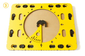
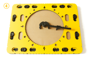
Another function of the wedge tool is to position the compass in the centre of the circle frame. You can achieve this by placing the wedge tool anywhere against the edge of the circle with the compass base against the flattened tip of the wedge. The centre of the compass base now hooks around the pen blocker at the tip of the wedge tool.
By slightly turning the base counter clockwise, it will catch the small protruding block on the curved side of the wedge. This way, the compass base is exactly in the middle of the circle. By removing the wedge tool and placing the compass arm into the base, you can draw a circle precisely in the centre of the circle frame.


Figure 2. Position the wedge tool along the edge of the circle (step 1), position the compass base and turn it so it rests against the wedge tool (steps 2 and 3) and remove the wedge tool (step 4). The compass is now perfectly positioned in the centre.

You can also combine the compass with the edge of the circle. The indents per five degrees are semi-circular and have the same diameter as the needle of the compass. After placing the compass base on the circle frame, you can slide the needle of the compass into one of the indents along the edge. The centre of the arcs are now exactly on the circle. By drawing multiple arcs along the edge of the circle, you can create intriguing repetitive geometric patterns.

Drawing the hands of a clock

Around the circle of the circle frame, multiples of 30 degrees are indicated by drop-shaped indentations. These make up for the twelve hours of the clock.
To draw a clock hand, you can use the wedge tool. Along the rounded side you will find grooves at an angle corresponding to 1 minute, or 6 degrees. The longer groove of 2 centimetre indicates the position of 5 minutes or 1 hour later. After placing the wedge tool with the rounded side against the edge of the circle and aligning the straight side with one of the hour indications, you can set the minute and draw the hands of the clock as radii and have it set at any desired time.


01. ClickPad – Audio-tactile images – Introduction

The TactileView ClickPad is a clipboard, on which a tactile image is placed. Combined with the TactileView digital pen and the TactileView software, the ClickPad functions as a touch screen. On this, a VIP (Visually Impaired Person) can explore an audio-tactile image; a tactile image that contains audible information as well. The digital pen is used as a click and point device similar to a computer mouse, and tells the computer on which position of the image has been clicked. The software then plays any audio information that is present at the clicked position.