Skip NavigationMenu

11.02 TactileView graphics suite products

Functions of the digital pen in the design mode and in the explore mode

In this section, the basic operation of the different products is described. In separate sections, the functionality will be explained when the pen and receiver are connected to create a drawing (design mode) or exploring a audio-tactile diagram (explore mode).

TactileView digital pen

The digital pen enhances the functionality of the TactileView software for a visually impaired user. It replaces and extends the use of a regular mouse.

The digital pen acts as a mouse to operate the software (by clicking opening menus and selecting options) or as a pen in a bordered area, similar to a digitizer.

The digital pen itself resembles an ordinary ballpoint pen. In the tip we can find a tiny transmitter that transfers a signal to a receiver. The receiver is placed alongside the TactiPad or the ClickPad and is connected via USB to the computer. Via the receiver, the position of where the pen is within the surface of the pad is transmitted. Just like a regular mouse, you can click by pressing down with the pen anywhere on the surface (the tip is pushed inward slightly).

See also the section ‘Operating the TactileView digital pen’.

TactiPad drawing board

The TactiPad can be used to create free-hand drawings or more exact drawings with the help of the tools (ruler, protractor, triangle and compasses). The GraphGrid and CircleFrame accessories extend the range of drawings that can be made even further. These devices can be used by all age groups, starting from the age of 4.

Depending on the age and the purpose of the diagram, it can be more exact for teaching basic concepts, for explaining and teaching math and science or for fun drawing in which preciseness is required. On the other hand, the TactiPad can also be used for a quick sketch.

The TactiPad is specifically useful as a valuable and convenient method of communication between a VIP and a sighted person.

See also www.tactipad.nl

TactileView ClickPad

The ClickPad holds printed audio-tactile diagrams (tactile graphics that contain audio information objects with audio style) and is available in various sizes for different paper sizes. For more information, read the section ‘What is an audio tactile diagram’.

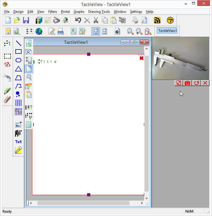
TactileView design – and production software

The software is in the first place aimed towards a sighted user. However, it is fully accessible with a screen reader. All menus and dialogs have short cut keys. The software has functionality to support screen reader users. Extra menus become available in the software when the digital pen is connected.

4.05 Capture scanner or webcam image

Using a scanner or a webcam offers a flexible method to quickly import existing material you’re your design. Both methods create a bitmap image that will need some processing to turn it into a tactile usable design.

Settings menu – Scanner and Webcam

Make sure the devices are configured in the settings menu dialogs ‘Webcam’ and ‘Scanner’. A message will indicate when your device is not connected or configured when you try to start it.

Scanner

The scanner will create an image (bitmap) of the scanned document. This way, you can use existing images from text books or documents as a basis for your tactile graphics.

‘Quick scan with scanner’ icon: Quick scan with scanner icon
Webcam

The video content from the selected webcam is displayed in a small window beside the drawing area. The control buttons are available below this window. You can adjust the size of the webcam window by clicking ‘Enlarge/reduce the webcam view’. Pressing the shutter button of the webcam (‘Take webcam snapshot’) will record a snapshot image. You can rotate the webcam image if necessary by clicking ‘Rotate the webcam view’, and shut the webcam window down with ‘Deactivate webcam’.

Existing document or new document

Once you have recorded your scanner or webcam image, you will be asked whether you want to add it to the existing design or insert it in a newly created design. The image will be placed in the top left corner of your design. As the image is inserted as a figure, the size and position of the image can be adjusted .

Further processing

As with all other images (copied from internet or imported from file) further processing is usually required.

– Retouching (pen and eraser): fusing the image with the design bitmap allows you to refine parts of the image.
– Apply filters: colours have to be removed and the image usually has to be converted to a line drawing.
– Use text labels: add a title and other text labels to clarify the different parts of the image

For a full description of the respective tools, see also the section ‘Drawing tools toolbar’.

‘Activate webcam’ icon: Activate webcam icon

A separate window within TactileView shows that the webcam is activated for capturing images

Figure 1. A separate window shows the webcam is activated for capturing images; click on the image to enlarge.

Webcam control icons

Figure 2. Webcam controls: ‘Enlarge webcam view’, ‘Take webcam snapshot’, ‘Rotate webcam view’ and ‘Deactivate webcam’.

1.01 System requirements and product details

System requirements Windows XP, Vista, 7, 8, 8.1 or 10; for Mac OS X, a Windows emulator is required
Licence One-time purchase, unlimited use
Delivery Registration key via email
Available languages Arabic, Chinese, Czech, Danish, Dutch, English, French, German, Hindi, Italian, Japanese, Korean, Norwegian, Polish, Portuguese, Russian, Spanish, Swedish, Turkish
File formats TactileView files (.bpx); import .txt, .svg, .jpg, .png, .bmp, .tiff or .gif
Internet requirements TactileView can be used offline, but specific functions (e.g. map maker, designs catalog) require internet access
Software security A registration key is valid for software registration on one computer only


Supported printers

Supported embossers Index (V2, V3 and V4), ViewPlus (all models), Enabling (all models), Elotype, Puma, Gemini, Mountbatten Brailler

6.11 Draw mammoth braille

The dots of braille characters normally have a fixed distance, but this can be enlarged. In TactileView, the greatly enlarged braille is called ‘mammoth braille’ to distinguish from Jumbo braille (braille with increased dot distance).

NOTE: Mammoth braille is not used to place braille texts in the design, but could be used for ‘fun’ applications such as writing a name in a large braille character type. The braille dots will be displayed in blue on screen. The character that is represented by the dots is shown in grey behind the braille dots.

To draw a large braille in the design, select the ‘Draw mammoth braille’ icon from the left vertical toolbar. Click in the design where you wish to place the mammoth braille. Enter the contents in the dialog that appears and click ‘OK’. You can use the purple markers to resize the enlarged braille.

‘Mammoth braille’ icon: Draw mammoth braille icon

Mammoth braille; large blue dots and grey text in the design

Figure 1. Mammoth braille inserted in the design.

Difference in braille dot size using mammoth braille

Figure 2. The dot size of mammoth braille can be enlarged, as opposed to regular braille.

‘Braille dot size’ icon: Mammoth braille dot size icon

6.12 Draw letters and digits

NOTE: Keep in mind that this drawing tool is not intended to present texts in braille, but as a tool to show the contours and shapes of visual text characters. Various font types and font sizes can be used to illustrate font attributes such as serif, italic or bold.

To draw a text in the design, select the ‘Draw letters and digits’ icon from the left vertical toolbar. Click in the design where you wish to place the large text. Enter the contents in the dialog that appears and click ‘OK’. You can use the purple markers to resize the text, which should be large enough for tactile use to distinguish the characters.

‘Draw letters and digits’ icon: Draw letters and digits icon

Large blue letters drawn using 'Draw letters and digits'

Figure 1. Add large text to your design with ‘Draw letters and digits’

Large blue texts with different font sizes

Figure 2. Font type and size for letters and digits can be adjusted.

‘Font type and size’ icon: Font type and size icon

6.10 Import (image from file, svg and figure)

There are several ways in which you can add an image to your TactileView design.

  • When you regularly use the same icons or images, ‘Add figure’
  • Saved SVG image files can be added with ‘Import SVG’
  • Saved jpg, png or other bitmap images are added with ‘Import image from file’

These import functions are activated by selecting ‘Import’ from the left vertical toolbar, then selecting the specific tool from the right vertical toolbar.

‘Import’ icon: Import icon
‘Import SVG’ icon: Import SVG icon
‘Import image from file’ icon: Import image from file icon

Add figure

Figures are image objects that are useful when you wish to reuse certain symbols and shapes (such as arrows, electrical symbols, more abstract shapes, etc) in multiple documents. Once you have activated the ‘Add figure’ drawing tool, a dialog will appear in which you can You can browse through the different categories and select the figure you wish to use.

Once you click ‘OK’ to confirm your choice, the figure will be visible at the position of your mouse. Click anywhere to place the figure as an object in your design.If the object is not the desired size when it appears in the design area, you can edit it by dragging the purple markers on the corners and sides.

Settings – personal figures folder
TactileView contains a set standard icons, symbols and other figures. By selecting ‘Figures’ from the Settings menu, you can also select additional folders that contain your personal sets image files that you can use as figures.

Select area – Save as figure
When using the Select area tool, you can select ‘Save as figure’ from the context menu or properties toolbar. This saves the selected area as a figure that can later be reused and will include the bitmap layer as well as any objects within the selection. Keep in mind that text labels are not included in the figure. See the manual section ‘Select area‘ for more information.

Add figure dialog

Figure 1. From the dialog, choose one of the figures to insert in your design; click on the image to enlarge.

Import SVG and Import image from file

Vector graphics (svg files) as well as bitmap image files (jpg, png, bmp, etc.) can be imported in your design by selecting ‘Import SVG’ or ‘Import image from file’. In the dialog that opens, browse to the image file you wish to use and double click or select ‘Open’ to confirm the selection. Next, click anywhere to place the image as an object in the design. You can use the purple markers on the corners in case the image needs to be resized.

10.04 Browsing and selecting objects (Tab or Shift+Tab)

All objects that have been placed in the design with one of the drawing tools are grouped in the objects list (Ctrl+M). From this list, the respective context menus can be opened to change the properties of the object.

You can select an object or text label in the design by choosing it from this list, then pressing ‘OK’.

Cycle through text labels and objects with Tab or Shift+Tab

To conveniently cycle through the objects and text labels that are present in the design, use Tab (cycle forward) or Shift+Tab (cycle backwards). One by one, the objects and text labels will get the focus (will be selected). The name and position of the object or label will be announced.

This way you can cycle from top to bottom through the design. If any objects are horizontally aligned, the objects further to the left will come first.

Use Ctrl+K or the enter key to open the context menu if you wish to make any changes to the object.

10.02 Settings – Speech

In most cases, screen reader users will have a speech output for general computer access. For specific applications, screen readers have functionality to monitor certain areas on the screen in order to provide speech output.

The TactileView software can also provide information that is helpful for a screen reader user from the status line of the software or info related to all the many tools and objects.

When the TactileView software is extended with the TactileView digital pen and either the TactileView ClickPad or the TactiPad drawing board, additional options for exploring audio-tactile diagrams or creating digital drawings become available.

The operation of these additional options greatly depends on using a screen reader. The speech settings are applied while using these extensions as well.

See also the sections in the category ‘Digital pen, TactiPad and ClickPad’

Language selection and Text-To-Speech (TTS)

Textlabels and messages are displayed in the language that was selected in the ‘Language’ dialog in the Settings menu.

For announcing these texts, a text to speech (TTS) synthesizer has to be selected. Microsoft supplies a few TTS engines with the Windows operating system. Extra TTS synthesisers can be installed from Eloquence, Nuance, L&H or other vendors.

Volume and rate

The volume and rate of spoken messages can be set to find a match with the volume and rate with the speech output of the screen reader. Use the ‘Speak’ button to test the selected voice, rate and volume.

Speak application messages (select checked)

The software can provide messages in addition to a screen reader. These messages contain status information about the drawing tools and properties of the objects. When you use TactileView with a screen reader, the option ‘Use text to speech for application messages and audio style’ should be checked.

Speak audio style or text label upon object selection (Select checked)

When an object gets the focus (is selected) the type of object and some properties are announced. For screen reader usage, ‘Speak audio style or text label upon object selection’ should be checked.

Text to speech for different languages

Some designs may contain texts in different languages, making the text to speech difficult to understand. If possible, it is best to use the TTS that matches the text label language.

For any languages in the list that show ‘not defined’, the default TTS synthesiser will be used. To apply a specific TTS synthesiser for a certain language, select the language from the list, then select the TTS you wish to use in the list below.

10.06 View – Show properties (Ctrl+J)

When an object is selected in the design, it can be very useful for screen reader users to get a quick list of all the properties. To can select an object in your design, choose either ‘Menu driven design’ from the Drawing tools menu (Ctrl+L), or ‘List of objects’ from the View menu (Ctrl+M). In either list, select the object and press ‘OK’. The object now has the selection. The properties list of the selected object can be opened by selecting ‘Show properties’ in the View menu, or by pressing Ctrl+J.

The list of properties include aspects such as size, position in the design, etc. Use the button ‘Speak properties’ to hear the properties in a spoken message. If you wish to make any changes to the object, choose ‘Open context menu’.