In TactileView, several tools are available to facilitate a precise design process and cope with regulations and conventions that specify the layout of a tactile diagram.
Once the design is printed and in the hands of the reader, the right-up marker is tactile marker in the top right corner. This right-up marker helps to find the correct orientation of the diagram without having to explore the tactile diagram itself. This way you can easily find out if the design should be read in a portrait or landscape orientation.
When the marker is presented in blue on screen, it will be printed. By clicking on the red marker in the top right corner of the screen, the right-up marker can be selected or unselected. Alternatively, you can select ‘Draw right-up marker’ from the design toolbar (right vertical toolbar when nothing is selected) or the design context menu.

Figure 1. The right-up marker as shown on screen.
‘Draw right-up marker’ icon: ![]()
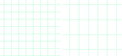
TactileView provides two alignment grids that make it easier to get the right layout in your document. The braille grid allows you to align text labels in a fixed grid throughout the design, whereas the measurements grid is used to visualise the dimensions in your document to align objects. The grids are shown in green on screen and will not be printed. You can enable or disable these grids in the second vertical toolbar. This option can also be found in the View menu.

Figure 2. A section of the measurements grid (left) and measurements grid.
‘Screen elements’ icon: ![]()
‘Show grid’ icon: ![]()
The graphic capabilities for tactile images differ for each individual production medium. Use the ‘Design mode: dot view/line view’ to control the layout for the different print outputs.
For accurate placement of texts in your tactile graphics, text labels can be aligned horizontally or vertically with other labels in the design. You can select ‘Switch text label alignment on/off’ from the properties toolbar of a selected text label, or when placing a new label in the design.
As long as the alignment function is on, green ‘magnetic’ dotted lines will appear when moving a text label close to the horizontal or vertical position of another label in the design. The text label on which the moved label will be aligned will be highlighted. When you let go at this position, the moved label will automatically ‘snap’ to this alignment. The same applies to placing a new text label in your design. Please note that aligned text labels are not ‘connected’ but can still be moved and edited separately.

Figure 3. Text label alignment with green dotted lines.
All objects in the toolbar tool have a ‘Centre’ option in their properties toolbar. With this option the object will move to the centre position of the paper. When the paper width is changed, the object will no longer be centred.
By holding the Shift key and dragging a selected object or textlabel, the movement will only be in a perfectly horizontal, vertical or diagonal direction. This can also be switched on or off permanently by selecting ‘Restrict to horizontal, vertical and diagonal movement’ from the properties toolbar or context menu of the object or label.

 Previous section
 Return to TactileView manual overview