Audio styles a great way to add more information to a drawing without having to make it larger to accommodate more text or graphical information. The audio information is accessed by using the file in explore mode, either on screen with a mouse or on a tactile copy on the Clickpad or Tactipad with the digital pen. For more information on explore mode, please refer to the Using Explore Mode and Using the Pen in Explore Mode with the Clickpad or Tactipad tutorials.
Audio styles can be added to any type of drawing object in TactileView (figures, squares, circles, dots, detected area, etc.). Audio styles may not be added to text labels, because text labels are automatically voiced by text-to-speech when the file is used in explore mode (the text contents of the label is used as an audio style).
Adding an audio style to be voiced by text-to-speech
To add an audio style to be voiced by text-to-speech to an object, select the object and then choose the ‘Audio style’ icon from the properties toolbar on the left side of the screen or right-click the object and choose ‘Audio style’ from the context menu. This will launch an audio style dialog, the top section of which allows you to specify the text to be voiced by synthetic speech from one of several sources.
The default choice is the ‘Self defined text’ radio button, which allows you to type the text you want voiced into the text field on the dialog. If you have text saved in a text file that you would like voiced instead, you can select the ‘Text from local file’ radio button, then choose the ‘Browse’ button to browse to and select your text file (.txt file). Once you have specified the text, you can check how the audio style will sound by selecting the ‘Test audio style’ button. When you are finished making changes, choose the ‘OK’ button to close the dialog and apply the audio style. The object will be shaded light pink to indicate that an audio style is associated with it.
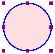
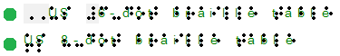
Figure 1. The light pink colour signifies an audio style is associated with the circle.
Attaching an existing sound file to an object
You can also attach an existing sound file to an object to have it played when the object is clicked while the file is in explore mode. In the audio style dialog, the bottom section allows you to specify a sound file to be used as an audio style.
The default choice is the ‘Local file’ radio button, which is used to attach a sound file to the object as an audio style. Select the ‘Browse URL’ button, locate the sound file you would like to use on your computer and select it. The file path to the sound file will now appear in the text field below the sound file type selection radio buttons. You can check how the audio style will sound by selecting the ‘Test audio style’ button. When you are finished making changes, choose the ‘OK’ button to close the dialog and apply the audio style. The light pink colour will now indicate an audio style is associated with the object.
NOTE:
If you have both a text-to-speech audio style and a sound file audio style attached to the same object, the text-to-speech will be voiced first and the sound file will play after it.
Recording an audio style from a microphone
Audio styles recorded from a microphone are played when the object is clicked with the mouse or digital pen while using the file in explore mode. Recorded styles are played after any text-to-speech styles are voiced. Before recording, you will need to ensure that you have a microphone connected to your computer. You can connect your microphone via the ‘Microphone’ dialog in the Settings menu.
When you have connected a microphone to your computer, you can record an audio style for an object by selecting the object, then choosing the ‘Record microphone’ icon from the properties toolbar on the left side of the screen, or by right-clicking the object and choosing ‘Record microphone’ from the context menu. As soon as you select this, recording begins and the icon in the tool bar changes to the ‘Stop recording’ icon. When you have finished speaking into the microphone, choose the ‘Stop recording’ icon from the tool bar or right-click the object and select ‘Stop recording’ from the context menu to stop the recording. Your recording will play back automatically as soon as you stop the recording, and the object will be shaded light pink to indicate that an audio style is associated with it.
NOTE:
Each object may only have one text-to-speech audio style and one recorded or sound file audio style associated with it. If you record an audio style for an object, it will replace any existing sound file you may have associated with that object previously.
Editing an existing audio style
To edit any type of audio style, select the object with the audio style you want to edit and then choose the Audio Style icon from the tool bar on the left side of the screen or right-click the object and choose Audio Style from the context menu. This will launch the same audio style dialog you used to create a text-to-speech audio style or attach an existing sound file.
To edit a synthesized speech audio style from self-defined text, edit the text in the text field. You can also remove the text-to-speech audio style by deleting the text from the text field in the top section of the dialog.
To edit a synthesized speech audio style from text from a local file, you will need to edit the text within the text file itself. To load text from a different file, select the Browse button, locate the new text file you would like to use and select it. You can also remove this audio style by deleting the file path to the local file from the text field in the top section of the dialog.
To edit an audio style played from a sound file, choose the ‘Browse URL’ button, browse to a different sound file on your computer and select it. It will replace the previous sound file, including any sound file recorded from a microphone, as the audio style for that object. To remove the sound file audio style, delete the file path of the sound file from the text field in the bottom section of the dialog.
When you are finished making changes, choose the ‘OK’ button to close the dialog and apply your changes.
If you would like to re-record an audio style from your microphone, simply follow the steps given above for recording from a microphone. You do not need to open the audio style dialog to do this. Please remember that recording an audio style for an object from the microphone will overwrite any other sound file audio style for that object.
 Previous section
 Return to TactileView manual overview