Some braille embosser models allow you to use different relief heights for the braille dots. In TactileView, this relief height can be applied to the blue objects (squares, blue lines, triangles, etc.) as well as the Detect shape tool, tables and graphs.
To find out which embossers are capable of embossing different dot heights, see: Properties of different braille embossers.
For a full overview of all object properties, see: Editing object properties.
Relief height: line, surface and texture
Normally, objects will be embossed using the highest dot height, as this usually gives the best tactile quality. In the case of image files, the colours of the image will be converted to different dot heights, where lighter colours result in lower dot height. This is the default setting for relief height and can always be selected as dot height by choosing ‘Standard’ as the value.
In TactileView, the relief height can be selected separately for the different components of objects. Firstly, you can select a dot height for the outline of the object. Secondly, the surface area of the object (i.e. the area within the outline of the object) can be given a separate height. Finally, if the object has a texture fill style, it can have a different relief height as well.
You can directly edit the relief height for the line, surface and texture by selecting ‘Relief height: line’, ‘Relief height: surface’ or ‘Relief height: texture’ from the properties toolbar or the context menu of the object. The dot height for the line can also be found in the ‘Line style’ dialog, whereas the dot height for the surface and texture can be found in the ‘Fill style: texture’ dialog.
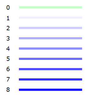
The different dot heights are shown in the design using different shades of blue: a lighter shade signifies a lower dot height, whereas a darker shade corresponds with a higher dot height.
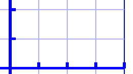
For graphs, you can select the relief height for the grid lines to make them less prominent and distinguish them from the axes and graph lines. By default, these grid lines will already have a lower value; you can edit the relief height by selecting ‘Size and position’ from the graph’s properties toolbar or context menu.

Figure 1. Different dot heights are shown with different shades of blue in the design.

Figure 2. The grid boxes in a graph have a lower dot height than the axes, as shown with the lighter blue colour.
Use contrast for tactile usability
Although the dot height can be set to 8 different heights, in reality the increments between these steps are very small. This means there will not be a distinguishable tactile difference between a dot height of 3 and 4. It is advisable to use sufficient contrast in relief height between different elements; for example, a value of 8 for the outline of an object and value of 2 for its surface.
Compatibility with other embossers
The relief height properties of objects are only available when you have a printer selected that supports variable dot height via menu File > Print Setup. A message will notify you when a document is opened that contains objects with variable relief height, but the selected embosser does not support this property. The variable relief height will still be visible in the design using lighter and darker shades of blue, but it is important to remember that the tactile output of the embosser or printer will differ: the outline and texture of the object will be embossed, but the relief height of the object’s surface will have no relief height.
In this situation, you can only edit the relief height for existing objects with a relief height not set to ‘default’. Once you set it to ‘default’, the relief height property of the object will no longer be available until you have an embosser selected that does support variable dot height.

 Previous section
 Return to TactileView manual overview