Skip NavigationMenu

03. Zigzag triangle

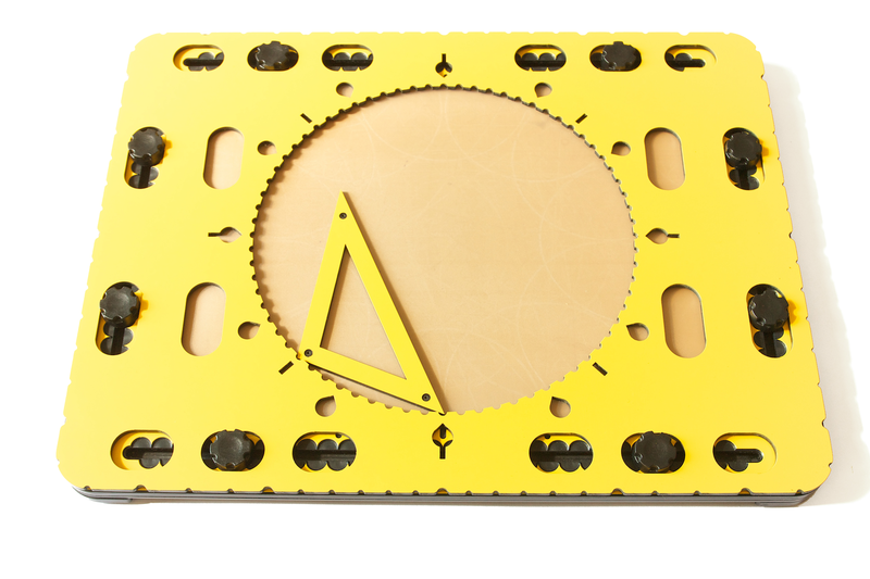
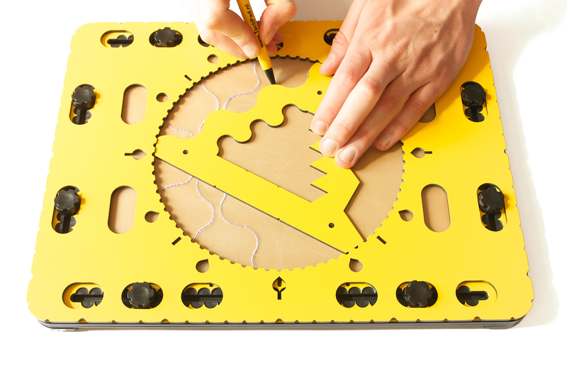
Photo: Zigzag triangle in the circle frame

The size of the zigzag triangle is such so that it fits exactly inside the 20 centimetres diameter of the circle.
The three sides of the body of the triangle all have a different pattern. The middle section of the triangle is open.
The inner sides do have the same patterns as the outside, at a smaller scale.
The zigzag triangle is also called a ‘Christmas tree’.

Detailed description

The corners of the triangle are rounded. One corner has an alignment indentation to align the triangle
with the degree markings along the edge of the circle. The side opposite the indented corner is straight.
Another one provides a smooth wave pattern, the final one has a zigzag pattern.
Along the inner and outer side of the straight side two small indents indicate the length of a line segment to construct a hexagon.
In the straight side oval holes can be found to hold a pen while rotating the triangle.
The holes are placed to obtain curves at four, five, six, seven, eight or nine centimetres relative to the centre of the circle.
Pushpin markers are placed near the corners.

Zigzag triangle manual

Preparing the TactiPad

Place all eight knobs of the TactiPad approximately five centimetres away from the corners. Place the circle frame on top of the TactiPad.

Using the zigzag triangle

The large zigzag triangle fits exactly inside the circle with the rounded corners nearly touching the circle edge. It can rotate freely.
Place your pointing finger on the alignment indent and align the triangle at 12 o’clock.

Equilateral triangle inside the circle

Start with the indented corner at 12 o’clock and draw along the straight outside of the triangle. Rotate the tool over 120 degrees clockwise (which is at 4 o’clock) and draw the line.
Rotate once more over 120 degrees (which is at 8 o’clock).

Hexagon in the circle

Align the indented corner at any degree indication and draw a line only between the two indents along the inner or outer straight side. Rotate the triangle over 60 degrees and repeat the draw.
In total four more rotations are required to finish the shape.

Repetitive patterns; Mandala type of figures
By tracing segments of the sides and/or combining patterns intriguing drawings will emerge. Whatever you do, the result is fascinating.
Zigzag triangle is used to draw intriguing shapes and repeating patterns

Photo: With the zigzag triangle you can create intriguing shapes and patterns.

Oval holes to create arches
The holes in the straight side of the triangle can hold a pen.
Rotate the triangle holding the pen.
Arches with a length depending on the amount of rotation and the selected radius will occur.

For detailed descriptions and manuals of related tools see:

Circle frame

468Triangle

Wedge tool

More ideas

04. 468Triangle

The small triangle tool is placed along the edge of the circle

Photo: 468Triangle

Detailed description

The 468Triangle is a triangular shaped frame with a width of one centimetre.
The main purpose is to serve as a template for ‘home made’ templates.
The inner space of the triangle is open.
The corners of the triangle are pointy so they fit in the indents at the edge of the circle of the framework.
The length of the sides are designed so they exactly span an arc of 45, 60 or 90 degrees, seen from the centre of the circle.
The ‘468’ refers to the number of rotations required for the triangle to return on the same position in the circle; four, six or eight times.
Pushpin markers are located at the top surface.

468Triangle Manual

The 468Triangle tool is intended to create your own drawing templates out of cardboard or other sturdy material.
Giving one side of the template a length similar to one of the triangle sides, it will fit by rotating eight, six or four times in the full 360 degrees of the CircleFrame.

Your template
Cut out an – irregular – shape from the centre of your template.
Place the template against the edge of the circle and trace the inner contour.
Depending on the chosen length, rotate the template 45, 60 or 90 degrees to obtain a symmetrical pattern.
Recurrence and/or partial overlap will give your drawing an unexpected appeal.

Alignment with indents from start to end

Because the side of your template has a specific length, it will by rotating the template eight, six or four times respectively, along the circle’s edge, end up at the starting position again.

The 468Triangle tool is placed along the edge of the circle

Photo: The 468Triangle tool is placed along the edge of the circle in the frame

02. Circle frame

The CircleFrame is the name of the product which includes the wedge tool, the 468 triangle and the zigzag triangle, and a frame with a large circle in the middle. The frame itself is called circle frame (no capitals).

Circle frame on the TactiPad

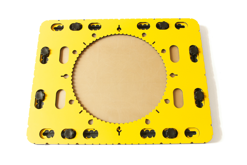
Photo: Circle frame positioned on the knobs of the TactiPad.

Detailed description of the circle frame

The circle frame has similar dimensions as the TactiPad (28 cm by 37 cm). The thickness of the frame is four millimetres.
Near the outer edge of the frame oval holes can be found to place the frame in one of three positions on the TactiPad.
For an a-centric position, two additional holes are present at both sides near the circle.
In the middle of the circle frame is a large circle cut out with a diameter of 20 centimetres. This is the actual drawing area for the drawings.
Along the edge of this circle clear tactile markings every five degrees are provided, which form a large protractor.
Around the outside of the circle there are extra markings: a teardrop shape for every 30 degrees, a line for every 45 degrees,
or a combination of both where they coincide at 0, 90, 180 and 270 degrees.
Indentations are placed around the outside of the circle frame in which rubber bands can be attached.
These indentations are positioned at every 10 degrees seen from the centre of the circle.
Slightly wider indents make the positions for 0, 30, 45, 60, 90 degrees, etc. easily recognizable

Circle frame manual

Because the circle is exactly in the middle of the circle frame, the frame is horizontally and vertically symmetrical. Therefore, there is no difference in shape between the yellow and black side. The orientation of the circle frame on the TactiPad therefore needs no consideration.

Preparing the TactiPad
Place the knobs of the TactiPad five centimetres away from the corners.
The circle frame can be placed in three different positions: in the middle of the drawing board with the edges coinciding with those of the TactiPad, or in two positions left and right of the centre when in landscape orientation.
Make sure the eight oval holes near the outer edge of the circle frame fit all over a knob.

Circle frame on the TactiPad

Photo: Indications run along the edge of the circle: small indents for every 5 degrees, drop shaped ones every 30 degrees and straight ones every 45 degrees.

Insert the tools in the circle
The wedge tool, your templates based on the 468triangle or the zigzag triangle can rotate freely over 360 degrees within the circle.
The drawing tools preferably are aligned with the degree markings along the circle.

For detailed descriptions and manuals of related tools see:

Zigzag triangle

468Triangle

Wedge tool

More ideas

3.04 Keyboard shortcuts

The following list of keyboard shortcuts are supported in TactileView. These shortcuts can be used to easily activate specific software functions, general operations, drawing tools and text editing functions. The list of shortcut keys for the drawing tools can be personalised to make them easier to remember (see below).

See Scroll wheel and key combinations for keyboard combinations with the scroll wheel.

TactileView shortcuts
Ctrl+B Fuse selected object with the bitmap
Ctrl+E Open current file in Explore mode: Speech and sound
Ctrl+I Play audio style
Ctrl+J Show properties of selected object
Ctrl+K Open context menu
Ctrl+L Start Menu driven design
Ctrl+R Explore colour composition
Ctrl+W Take webcam snapshot when activated

Drawing tools (default set, see below for personalisation)
T Text label
S Select area
H Detect shape
F Filters
U Retouching – adding lines
E Retouching – eraser
L Draw straight line
Q Draw Square-Rectangle
C Draw Circle-Ellipse
N Draw Triangle
P Draw Polygon
D Draw free hand line or closed shape
O Draw Dots
A Draw Table
G Draw Graph
I Import
M Mammoth braille
R Draw letters and digits
V Add voice memo

General shortcuts
Ctrl+N New document
Ctrl+O Open document
Ctrl+S Save
Ctrl+Shift+S Save as
Arrow keys Move object or anchor point by 1 pixel
Shift+Arrow keys Move object or anchor point by 10 pixels
Ctrl+X Cut
Ctrl+C Copy
Ctrl+P Print
Ctrl+Z Undo
Page Up Jump to previous page
Page Down Jump to next page
Esc Deactivate currently active drawing tool/deselect currently selected object
Ctrl+Tab Switch between open designs

Text editing
Home Jump to front of text line
End Jump to end of text line
Ctrl+Home Jump to start of text label
Ctrl+End Jump to end of text label
Shift+Arrow keys Select text
Shift+Left mouse click Select text between caret position and click position
Del or Backspace Delete selected text

Personalised drawing tools shortcuts

Via menu Settings > Keyboard shortcuts, the list of shortcuts that activate the drawing tools in the left vertical toolbar can be edited. The left column in the dialog contains the list of drawing tools; by clicking on the right column, you can assign a keyboard key that will act as the shortcut for the corresponding drawing tool. You can always return to the default list of shortcut keys by clicking on the ‘Reset default shortcut keys’ button.

Remember that each shortcut key can be used only once in the list, giving each drawing tool a unique key.

12.04 Effect of printing properties on tactile usability

The tactile characteristics vary significantly between the different printing methods that are supported in TactileView. These differences have major influence on the tactile usability (how easily elements can be distinguished) of a design.

The printing methods can be divided into three broad groups: embossers with dots in a fixed matrix pattern, embossers with floating graphics and swellpaper. See Properties of different braille embossers for an overview of the properties of each supported embosser model.

Read the Drawing tools section in the TactileView manual to learn how to adjust the properties of the drawing tools, such as filters, retouching tools and the line thickness, line style and textures of objects.

Printing properties - effects on tactile usability

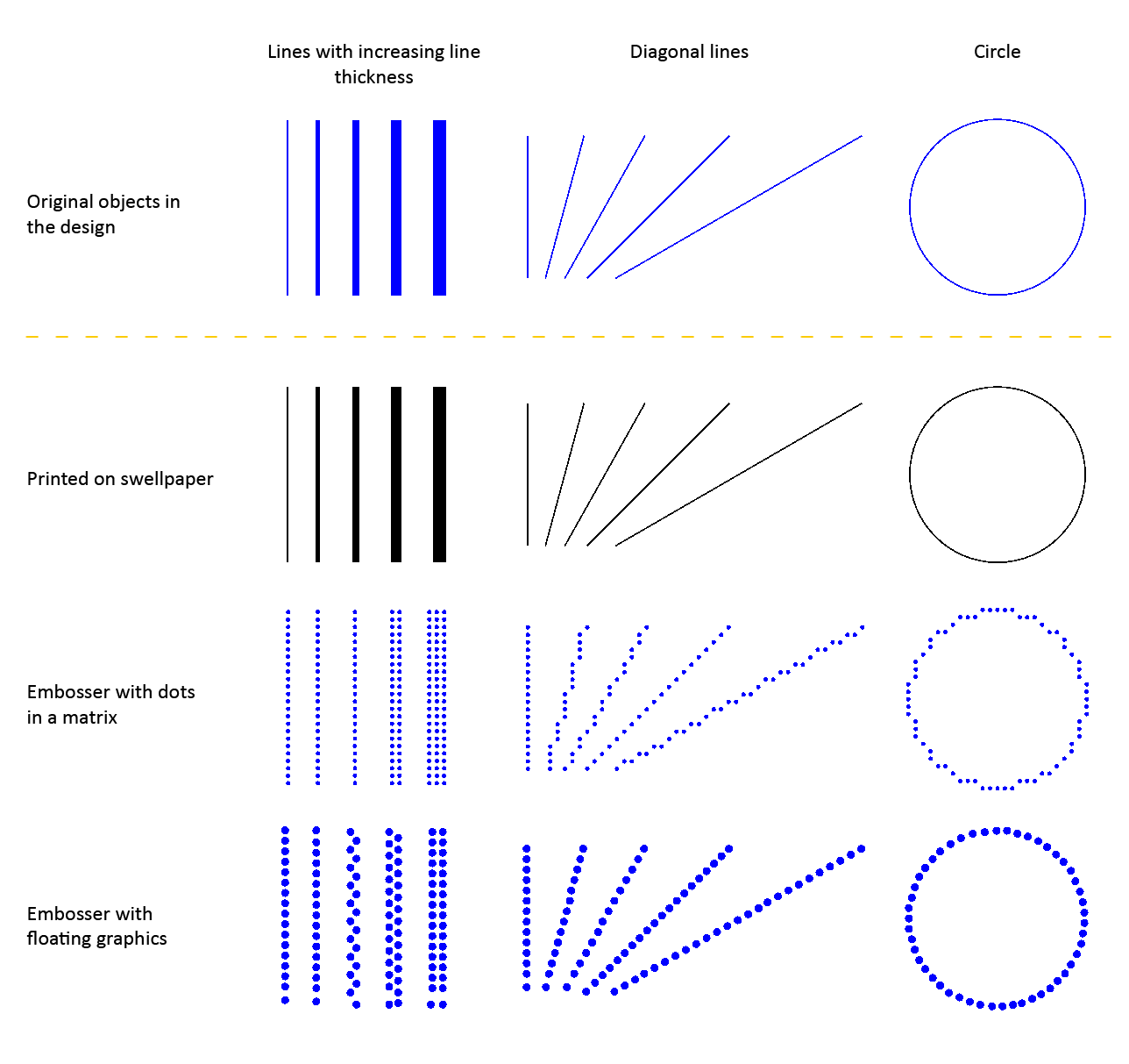
Figure 1. Comparison between the tactile properties of different printing methods.

Embossers with fixed dot matrix

In many braille embossers, the positioning of the dots that form the tactile graphic is limited to a matrix pattern of braille dots with a fixed distance between the rows/columns dots. The tactile graphics are limited to a comparatively low resolution because of the minimum size of a braille dot and their placement in the matrix. An empty space of at least 1 braille dot (or preferably more) is required to distinguish between neighbouring lines and shapes.

Line thickness Limited to a multiple of dots with a minimum of 1 braille dot
Diagonal lines and curves Composed of small  vertical and horizontal line sections
Distance between lines Minimum of 1 braille dot between neighbouring lines
Line styles Limited to relatively coarse line styles, as the gaps and dashes in the line pattern need to be at least the size of 1 braille dot
Textures Limited to coarse textures due to the matrix pattern and minimum size of texture lines/elements and the empty space between them

Embossers with free dot positioning

A number of braille embossers do not have a fixed dot matrix but instead allow the dots to be placed anywhere on the page with high accuracy. This way, the dots can follow curves very accurately. The size of the braille dots still limits the level of detail to a certain degree in order to avoid overlap with adjacent dots.

Line thickness Minimum thickness of 1 braille dot, with undulating ('zigzag') lines or multiple
Diagonal lines and curves Perfect diagonal lines and curves due to the floating point positioning
Distance between lines Can be positioned freely, but an empty space of at least the thickness of a braille dot is recommended
Line styles Limited to relatively coarse line styles, as the gaps and dashed in the line pattern have to be at least the size of 1 braille dot
Textures The minimum size of texture lines/elements and the distance between them results in a relatively coarse texture

Swellpaper

When printing on swellpaper, the TactileView design is printed directly in ink without any reduction in resolution (in contrast to the lower resolution of braille dots). This enables you to use fine details that are still distinguishable by touch.

Line thickness Can be varied in steps of 1 pixel
Diagonal lines and curves Perfect curves without limitations
Distance between lines Relatively small gaps between adjacent lines can still be distinguished due to the high resolution
Line styles Detailed line styles can be used as the minimum size of gaps and line segments can be very small
Textures Detailed textures can be used as the minimum size of the texture lines/elements and the empty space in between can be very small

Variable relief height for enhanced tactile usability

Some embossers support variable dot height as an additional method of distinguishing the lines in your design. For example, a lower dot height is applied to the grid lines in a graph in order to discriminate them from the axes and formula line.

This functionality is only available when supported by your embosser; see Properties of different braille embossers for an overview of embossers that support variable dot height and Editing object properties to find out how to apply variable dot height.

2.04 Registration for multiple user accounts on single computer

Your Software Registration Code (SPC), the registration code with which the TactileView software is registered, is valid for registration on one computer. However, multiple user accounts on the same computer can all make use of the same SPC to register TactileView.

Computer registration - 'All users (requires administrator rights)' or 'Current user only'

There are two ways to complete the registration for each Windows user account on the computer:

  1. Register for all users. This requires a Windows account with administrator rights. During registration, choose ‘All users’ to activate the registration for all user accounts on the same computer simultaneously.
  2. Current user only. This option can be used when you have no administrator rights. However, the registration will need to be repeated using the same SPC for all other user accounts that wish to use TactileView.

For full installation and registration instructions, see Installing software and Software registration with software product code (SPC).

2.01 Configuration wizard

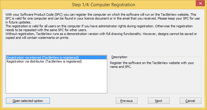
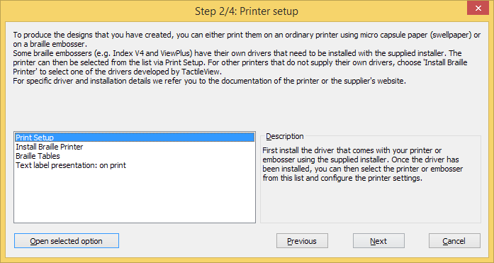
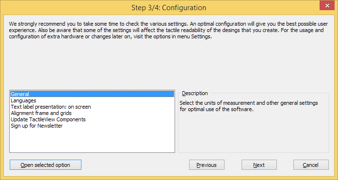
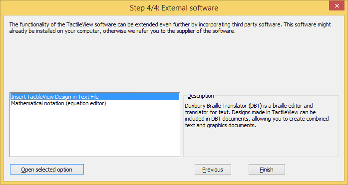
Once TactileView has been installed, you will be prompted with the Configuration wizard, which will guide you through registration and the most important settings for optimal use of the software. Each of the 4 steps in the configuration wizard are ‘Computer registration’, ‘Printer setup’, ‘Configuration’ and ‘External software’. In each step, there is a list with the essential settings. By selecting one from this list, you can read the description on the right. Click on ‘Open selected option’ to go to the selected settings dialog.

You can launch the Configuration wizard at any time later on by selecting it from the Help menu.

In the manual section Settings menu, you can find a more detailed list of all the settings menu option.

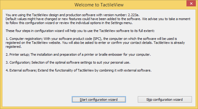
Configuration wizard introduction: overview of the steps in the wizard

Configuration wizard: Introduction. This window gives an overview of the different steps in the configuration wizard. Click on ‘Start configuration wizard’ to proceed.

Configuration wizard step 1/4, available options: Registration via internet; Registration via distributor.

Configuration wizard step 1/4: Computer registration. In this step, you can register your software licence.

Configuration wizard step 2/4, available options: Print setup; Install braille printer; Braille tables; Text label presentation on print.

Configuration wizard step 2/4: Printer setup. This second step will help you to configure the steps required for printing your tactile designs.

Configuration wizard step 3/4, available options: General; Languages; Text label presentation on screen; Alignment frame and grids; Update TactileView components; Sign up for newsletter.

Configuration wizard step 3/4: Configuration. All basic settings for operating the software are included in this third step.

Configuration wizard step 4/4, available options: Insert TactileView design in text file; Mathematical notation (equation editor).

Configuration wizard step 4/4: External software. This final step will help you to extend the functionality of TactileView with external software.

2.02 Software registration with SPC via internet

Once you have downloaded and installed the TactileView software, it will operate in demonstration mode at first. To run the software in full version, a software product code (SPC) is required. This SPC is provided by your dealer or has been sent by email after you purchased a software licence in the Thinkable shop. Download TactileView

The easiest and fastest method to register the software with your SPC is registration via the internet. However, TactileView also provides a registration option that does not require an internet connection; see Software registration via distributor (no internet access).

Each SPC is valid for one computer only. If you wish to use TactileView on multiple systems, you will need to purchase additional SPCs. For registration on multiple user accounts on the same computer, see Registration for multiple user accounts on single computer.

Software Product Code (SPC)

You will need to register the software using a Software product code (SPC) in order to get access to the complete set of software features. After purchasing a TactileView software licence, you will receive an SPC, either by email from the TactileView website, in a licence document from your dealer, etc. Make sure to store this code carefully, as you might need it later on for software updates or customer support.

Registration steps

  1. Select ‘Registration via internet’ in step 1 of the Configuration wizard. Alternatively, choose ‘Computer registration’ from the Settings menu and make sure ‘Registration via internet’ is selected in the dialog that opens.
  2. Enter your SPC, choose a User/company name and click on ‘Register now’.
  3. Choose whether you wish to register the software for all users on the computer (requires administrator rights) or the current user only.
  4. Enter and confirm the required contact details for customer support and optimal use of the software. You are now ready to start using the fully registered TactileView software.

12.07 Troubleshooting common printing issues

This page collects the most common errors that can occur when embossing TactileView designs.

Index embossers – Paper length settings in Index firmware (Error 213)

When printing a TactileView design using Index V4 embossers with firmware version 1.5.3 or earlier, the embosser may prompt you with an audible ‘Error 213’ message. This is caused by an incorrect maximum number of lines per page in the firmware of the embosser. For example, the firmware uses 26 instead of the correct 27 lines for letter or 11 inch paper, or 28 instead of 29 lines for A4 paper.

Read more

When you select an Index V4 embosser in File > Print setup, you will be prompted with a ‘Paper length settings in Index firmware’ dialog that allows you to avoid or solve this error. You can also access this dialog via Help > Configuration wizard, then proceed to step 2.

To test whether you will encounter this error when embossing, first make sure to select the same paper size in TactileView and in the embosser. Next, click the button ‘Test printer for error 213’ and wait at least 10 seconds. If you hear no error message from the embosser, you do not have to take any further action and will not encounter the error when embossing a design. If you are prompted with error 213 however, press the ‘Off’ button on the embosser control panel and follow these steps:

1. Update the embosser firmware to firmware version 1.5.4 or higher. Check the Index website for availability and instructions.

2. If updating the firmware is not possible, follow the instructions on the Index website on ‘Error 213 – How to adjust to fit DBT lines/page’.

3. If step 1 and 2 do not resolve the problem, you can temporarily reduce the number of lines per page in your TactileView designs. To do this, select ‘Reduce TactileView design height by 1 line per page’ in the ‘Paper length settings in Index firmware’ dialog. Important: if you execute step 1 or 2 later on, you will have to make sure the reduced design height option is no longer selected.

Index embossers – Error caused by mismatched paper size settings

When printing on an Index braille embosser, it is important to match both the design size and settings in the embosser with the size of paper you wish to print on. If these settings do not match each other, the embosser will report an error and the document will not be embossed correctly or will not be printed at all.

Read more

To solve this problem, check whether all paper size settings are set to the correct paper size. In TactileView, go to File > Print Setup and select the desired paper size.

Please read the Index Braille manual for your embosser for specific instructions on entering the right page formatting settings in your embosser model.

12.03 Embosser driver installation

In TactileView, a wide variety of different braille embossers is supported (for an overview of their embossing properties, see Properties of different braille embossers).

It is essential to install the corresponding printer driver for your embosser model in order to produce the correct tactile graphics. The two steps of the ‘Embosser driver installation’ dialog will guide you through the installation of the correct driver.

TactileView driver versus manufacturer supplied driver

Some embossers require installing a driver that is supplied by the manufacturer. For the remaining supported embossers, TactileView supplies a specialised graphics driver.
To install the correct driver for your embosser model, open the dialog by selecting menu File > Install printer driver. In the first step you will be prompted with the list of supported braille embossers. Choose your particular model from the list, then click ‘Next’. In the second step, depending on your embosser type, you can either directly install the TactileView driver, or follow the written instructions to install a driver supplied by the manufacturer.

Option 1 – Driver supplied by TactileView

Some embossers are capable of creating tactile graphics, but are not supplied with a driver that supports this by default. In these cases, TactileView supplies a separate driver that needs to be installed via step 2 of the ‘Embosser driver installation’ dialog.
Please note that some models require additional settings, such as language selection. If required, this will be presented in the dialog.

Option 2 – Driver supplied by manufacturer

For a number of embossers, the driver that is supplied by the manufacturer also supports producing tactile graphics with TactileView. In this case, the driver will not be installed via TactileView, but using an installer file (.exe) that you receive with your embosser or download from the supplier’s website.
You will find complete instructions in step 2 of the ‘Embosser driver installation’ dialog for the installing driver and selecting the embosser in TactileView.