However, in order to use a software version of this generation in full mode, your software license needs to be eligible. You can check here if you already have such a license. (You need your software product code (SPC) for this. You can find it in the menu ‘Help’ > ‘About TactileView’.)
If your license is already eligible:
First, check the TactileView version you have installed already. Go to the menu ‘Help’ > ‘About TactileView’ and check if the version number starts with 2.5 . In this case, there is nothing you need to do.
If you have a lower version, go to the menu ‘Help’ > ‘Check for New Updates and Release Notes’.
Alternatively, you can download the latest software installation file and start the installation process by opening it.
If your license is not yet eligible:
Option 1: Use our webshop
Purchase an SPC upgrade in our webshop. You will receive and email with instructions and a key (code) which can make your SPC eligible to use TactileView generation 2.5 .
After making your SPC eligible, you can either go to the TactileView menu and select ‘Settings’ > ‘Update TactileView Components’ and choose ‘Check for new software updates’.
Alternatively, you can download the latest software installation file and start the installation process by opening it.
Option 2: Ask your distributor
Contact your distributor and request a license upgrade for your SPC. When your request has been processed, you will receive an email to inform you that your SPC is now valid for the upgrade to TactileView generation 2.5 . In this email you will find a download link to the latest version.
In the first tutorial, we covered how to produce a tactile graphic based on an image file by applying one or more image filters. However, not all images are suited for this method, and an adequate image might not always be available. In this tutorial, we will show the most effective way to produce a tactile graphic based on an image file when filters will not do the trick.
Reasons why filters might not work
In the manual section Importing images from the internet, we describe how to select an image that is most suitable for conversion with filters. However, suitable image files are simply not always available. For example, the quality of the tactile graphics can differ based on the level of detail – too much detail, and the elements are no longer distinguishable by touch; too little detail, and the subject might not come across clearly. In other cases, elements such as texts, colour gradients or shadows might disturb or complicate the tactile graphic. When an alternative, more suited image is not available, you will have to carry out additional editing to produce a good quality tactile graphic.
Tracing the image
With the Draw path – Curved shape tool that is introduced in TactileView version 2.500, it is easy to trace the required elements in an image. You can accurately match the curves and shapes in the images that you wish to present in the tactile graphic. Another added benefit of this method is that the path is an object (as signified by its blue colour), which means that you have full control over properties such as line style and can scale the elements to any size if required.
To see how we edited an image using the ‘Draw path – Curved shape’ tool, watch the video or scroll down for step by step instructions.
Step by step guide
1. Import the image
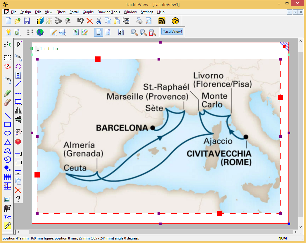
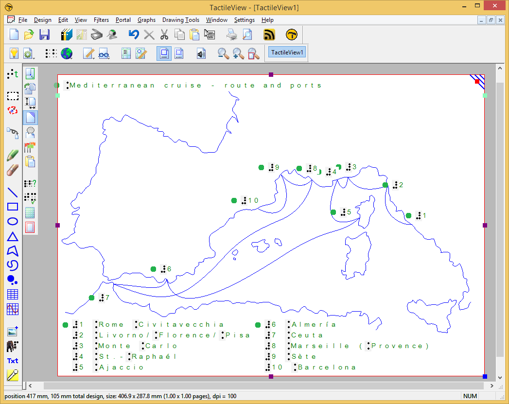
Place the image that you wish to use in your TactileView design by selecting ‘Import’ from the drawing tools on the left, then select ‘Import image from file’. Resize the image to suit the selected paper size. In this tutorial, we will use a map of a cruise holiday as an example.
2. Tracing elements in the image
Choose which elements you need to trace in the image to convert it to a tactile graphic. In our example, we will be tracing the contours of the coastline as well as the route of the cruise. The coastline of the islands will be traced as a separate element.
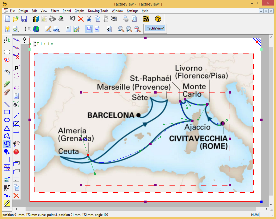
To start tracing the elements in the image, select the ‘Draw path – curved shape’ drawing tool from the drawing tools toolbar and choose ‘Click and draw (Bezier curve)’. Position the cursor at the start of the line, then click and drag to place the first anchor point. The direction in which you drag determines the direction of your curved line. Move to the first point along the line where it changes direction and place the next anchor point by clicking and dragging.
3. Finishing the traced line
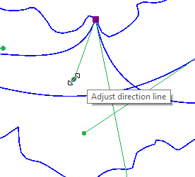
Once you have placed all the anchor points along the line in the image, click on the green semicircle that is visible next to the last placed anchor point.
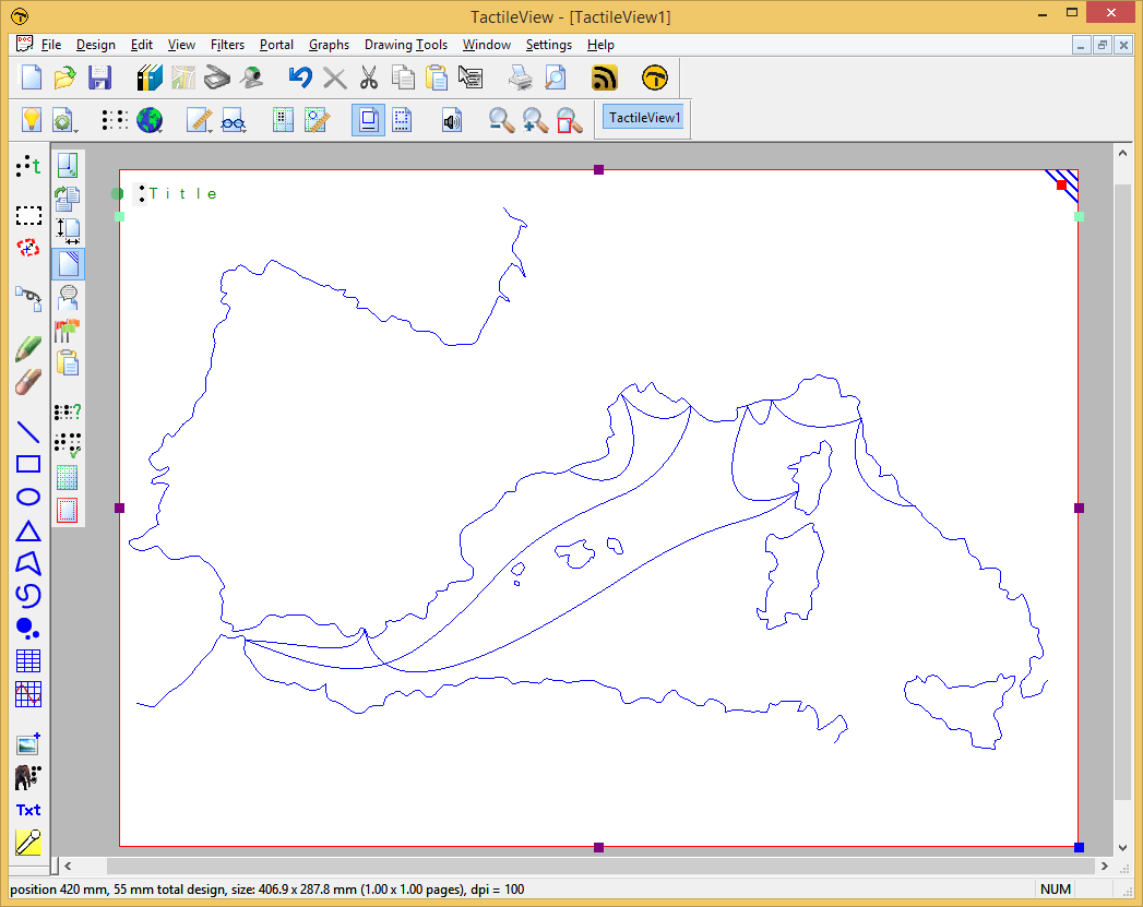
4. Remove the image file
Once you are finished tracing the image, you can remove it again by selecting it and pressing the Delete key.
5. Refining the lines
You can always refine the contours of the line that you created by adjusting the green handles at the anchor points. For the best accuracy, it is best to switch to ‘Design mode: dot view’ in the lower horizontal toolbar to check the exact positioning of the braille dots.
6. Apply braille text labels
Most tactile graphics gain a lot of clarity by using text labels to mark the different elements in the image. In our example, the cities along the route are labeled with numbers in the map, with the city names listed below.
7. Applying line styles and other properties
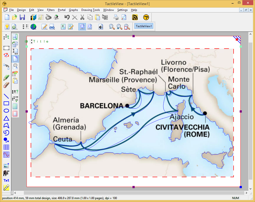
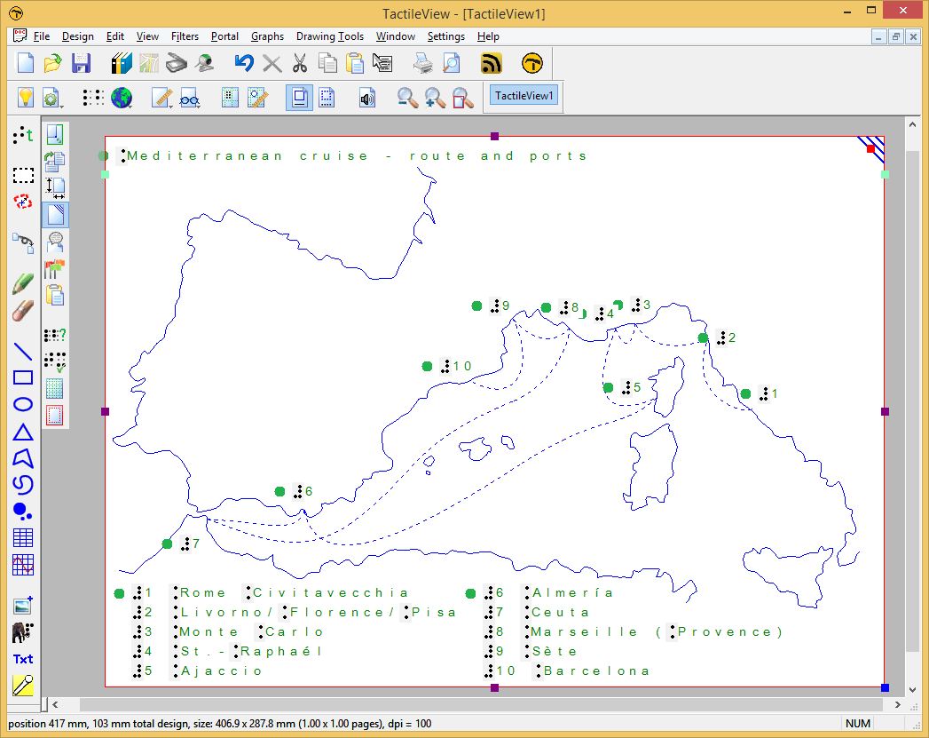
Once the elements of the image are traced, we have the added benefit that we can apply a range of properties to the different sections of the image. In our example, we can give the route of the cruise a different line style to distinguish it from the lines that mark the coastline. To do this, select the curved line object of the cruise route, then select ‘Line style’ from the properties toolbar and select a line style.
You could also choose to fill the land in the map with a texture to make it easier to feel the difference between land and water.
Some braille embosser models allow you to use different relief heights for the braille dots. In TactileView, this relief height can be applied to the blue objects (squares, blue lines, triangles, etc.) as well as the Detect shape tool, tables and graphs.
Normally, objects will be embossed using the highest dot height, as this usually gives the best tactile quality. In the case of image files, the colours of the image will be converted to different dot heights, where lighter colours result in lower dot height. This is the default setting for relief height and can always be selected as dot height by choosing ‘Standard’ as the value.
In TactileView, the relief height can be selected separately for the different components of objects. Firstly, you can select a dot height for the outline of the object. Secondly, the surface area of the object (i.e. the area within the outline of the object) can be given a separate height. Finally, if the object has a texture fill style, it can have a different relief height as well.
You can directly edit the relief height for the line, surface and texture by selecting ‘Relief height: line’, ‘Relief height: surface’ or ‘Relief height: texture’ from the properties toolbar or the context menu of the object. The dot height for the line can also be found in the ‘Line style’ dialog, whereas the dot height for the surface and texture can be found in the ‘Fill style: texture’ dialog.
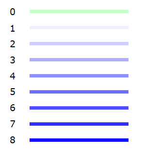
The different dot heights are shown in the design using different shades of blue: a lighter shade signifies a lower dot height, whereas a darker shade corresponds with a higher dot height.
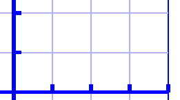
For graphs, you can select the relief height for the grid lines to make them less prominent and distinguish them from the axes and graph lines. By default, these grid lines will already have a lower value; you can edit the relief height by selecting ‘Size and position’ from the graph’s properties toolbar or context menu.
‘Relief height: line, surface and texture’ icons:
Figure 1. Different dot heights are shown with different shades of blue in the design.
Figure 2. The grid boxes in a graph have a lower dot height than the axes, as shown with the lighter blue colour.
Use contrast for tactile usability
Although the dot height can be set to 8 different heights, in reality the increments between these steps are very small. This means there will not be a distinguishable tactile difference between a dot height of 3 and 4. It is advisable to use sufficient contrast in relief height between different elements; for example, a value of 8 for the outline of an object and value of 2 for its surface.
Compatibility with other embossers
The relief height properties of objects are only available when you have a printer selected that supports variable dot height via menu File > Print Setup. A message will notify you when a document is opened that contains objects with variable relief height, but the selected embosser does not support this property. The variable relief height will still be visible in the design using lighter and darker shades of blue, but it is important to remember that the tactile output of the embosser or printer will differ: the outline and texture of the object will be embossed, but the relief height of the object’s surface will have no relief height.
In this situation, you can only edit the relief height for existing objects with a relief height not set to ‘default’. Once you set it to ‘default’, the relief height property of the object will no longer be available until you have an embosser selected that does support variable dot height.
When you are unable to connect to the internet with the computer on which you wish to register TactileView, you can register your software licence via your distributor. For regular registration via internet, see Software registration with SPC via internet.
Select ‘Registration via distributor’ from step 1 of the Configuration wizard. Alternatively, choose ‘Computer registration’ from the Settings menu and make sure that ‘Registration via distributor’ is selected in the dialog that opens.
Supply your distributor with the following information:
– Your SPC
– A user or company name
– Version number and Computer identification code (both can be copied from the registration dialog)
– Contact details: full name*, company, address, country* and email address* (information with an asterisk* is required)
Your supplier will contact the TactileView development team and provide you with a Registration code that can be used to register without an internet connection. Enter your SPC, a user or company name, and the received Registration code in the Settings > Computer registration dialog. Once you have filled this all in, select ‘Register now’.
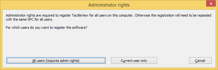
You are now ready to start using the fully registered TactileView software. The registration is valid for all users on this computer if you have administrator rights during registration. Otherwise the registration needs to be repeated with the same SPC for other users.
The following list of keyboard shortcuts are supported in TactileView. These shortcuts can be used to easily activate specific software functions, general operations, drawing tools and text editing functions. The list of shortcut keys for the drawing tools can be personalised to make them easier to remember (see below).
Open current file in Explore mode: Speech and sound
Ctrl+I
Play audio style
Ctrl+J
Show properties of selected object
Ctrl+K
Open context menu
Ctrl+L
Start Menu driven design
Ctrl+R
Explore colour composition
Ctrl+W
Take webcam snapshot when activated
Drawing tools (default set, see below for personalisation)
T
Text label
S
Select area
H
Detect shape
F
Filters
U
Retouching – adding lines
E
Retouching – eraser
L
Draw straight line
Q
Draw Square-Rectangle
C
Draw Circle-Ellipse
N
Draw Triangle
P
Draw Polygon
D
Draw free hand line or closed shape
O
Draw Dots
A
Draw Table
G
Draw Graph
I
Import
M
Mammoth braille
R
Draw letters and digits
V
Add voice memo
General shortcuts
Ctrl+N
New document
Ctrl+O
Open document
Ctrl+S
Save
Ctrl+Shift+S
Save as
Arrow keys
Move object or anchor point by 1 pixel
Shift+Arrow keys
Move object or anchor point by 10 pixels
Ctrl+X
Cut
Ctrl+C
Copy
Ctrl+P
Print
Ctrl+Z
Undo
Page Up
Jump to previous page
Page Down
Jump to next page
Esc
Deactivate currently active drawing tool/deselect currently selected object
Ctrl+Tab
Switch between open designs
Text editing
Home
Jump to front of text line
End
Jump to end of text line
Ctrl+Home
Jump to start of text label
Ctrl+End
Jump to end of text label
Shift+Arrow keys
Select text
Shift+Left mouse click
Select text between caret position and click position
Del or Backspace
Delete selected text
Personalised drawing tools shortcuts
Via menu Settings > Keyboard shortcuts, the list of shortcuts that activate the drawing tools in the left vertical toolbar can be edited. The left column in the dialog contains the list of drawing tools; by clicking on the right column, you can assign a keyboard key that will act as the shortcut for the corresponding drawing tool. You can always return to the default list of shortcut keys by clicking on the ‘Reset default shortcut keys’ button.
Remember that each shortcut key can be used only once in the list, giving each drawing tool a unique key.
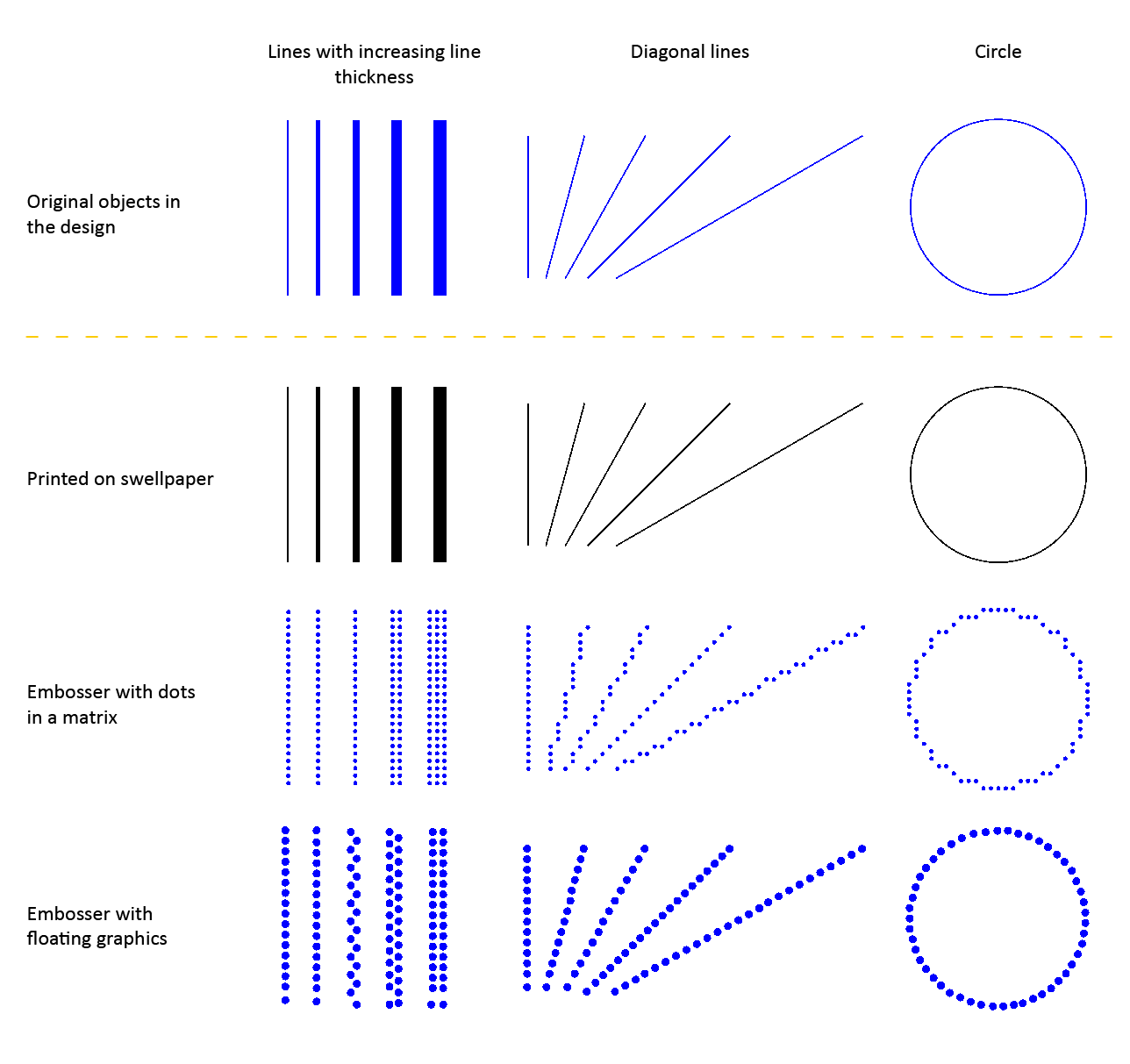
The tactile characteristics vary significantly between the different printing methods that are supported in TactileView. These differences have major influence on the tactile usability (how easily elements can be distinguished) of a design.
The printing methods can be divided into three broad groups: embossers with dots in a fixed matrix pattern, embossers with floating graphics and swellpaper. See Properties of different braille embossers for an overview of the properties of each supported embosser model.
Read the Drawing tools section in the TactileView manual to learn how to adjust the properties of the drawing tools, such as filters, retouching tools and the line thickness, line style and textures of objects.
Figure 1. Comparison between the tactile properties of different printing methods.
Embossers with fixed dot matrix
In many braille embossers, the positioning of the dots that form the tactile graphic is limited to a matrix pattern of braille dots with a fixed distance between the rows/columns dots. The tactile graphics are limited to a comparatively low resolution because of the minimum size of a braille dot and their placement in the matrix. An empty space of at least 1 braille dot (or preferably more) is required to distinguish between neighbouring lines and shapes.
Line thickness
Limited to a multiple of dots with a minimum of 1 braille dot
Diagonal lines and curves
Composed of small vertical and horizontal line sections
Distance between lines
Minimum of 1 braille dot between neighbouring lines
Line styles
Limited to relatively coarse line styles, as the gaps and dashes in the line pattern need to be at least the size of 1 braille dot
Textures
Limited to coarse textures due to the matrix pattern and minimum size of texture lines/elements and the empty space between them
Embossers with free dot positioning
A number of braille embossers do not have a fixed dot matrix but instead allow the dots to be placed anywhere on the page with high accuracy. This way, the dots can follow curves very accurately. The size of the braille dots still limits the level of detail to a certain degree in order to avoid overlap with adjacent dots.
Line thickness
Minimum thickness of 1 braille dot, with undulating ('zigzag') lines or multiple
Diagonal lines and curves
Perfect diagonal lines and curves due to the floating point positioning
Distance between lines
Can be positioned freely, but an empty space of at least the thickness of a braille dot is recommended
Line styles
Limited to relatively coarse line styles, as the gaps and dashed in the line pattern have to be at least the size of 1 braille dot
Textures
The minimum size of texture lines/elements and the distance between them results in a relatively coarse texture
Swellpaper
When printing on swellpaper, the TactileView design is printed directly in ink without any reduction in resolution (in contrast to the lower resolution of braille dots). This enables you to use fine details that are still distinguishable by touch.
Line thickness
Can be varied in steps of 1 pixel
Diagonal lines and curves
Perfect curves without limitations
Distance between lines
Relatively small gaps between adjacent lines can still be distinguished due to the high resolution
Line styles
Detailed line styles can be used as the minimum size of gaps and line segments can be very small
Textures
Detailed textures can be used as the minimum size of the texture lines/elements and the empty space in between can be very small
Variable relief height for enhanced tactile usability
Some embossers support variable dot height as an additional method of distinguishing the lines in your design. For example, a lower dot height is applied to the grid lines in a graph in order to discriminate them from the axes and formula line.
Your Software Registration Code (SPC), the registration code with which the TactileView software is registered, is valid for registration on one computer. However, multiple user accounts on the same computer can all make use of the same SPC to register TactileView.
There are two ways to complete the registration for each Windows user account on the computer:
Register for all users. This requires a Windows account with administrator rights. During registration, choose ‘All users’ to activate the registration for all user accounts on the same computer simultaneously.
Current user only. This option can be used when you have no administrator rights. However, the registration will need to be repeated using the same SPC for all other user accounts that wish to use TactileView.
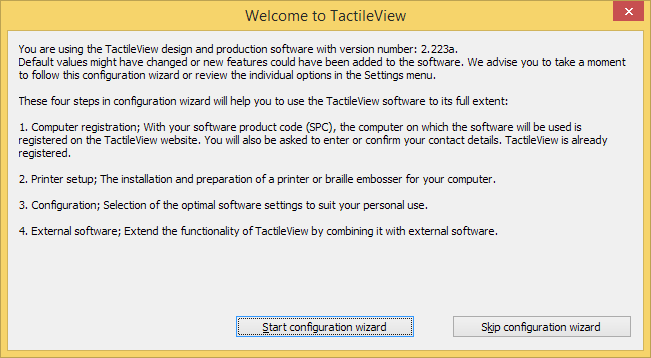
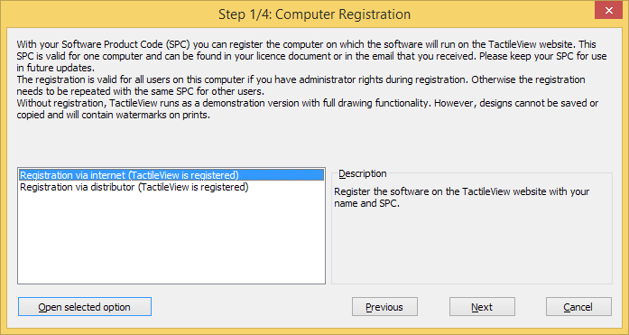
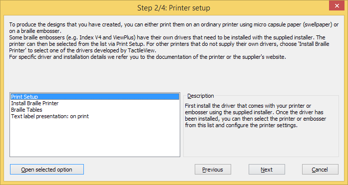
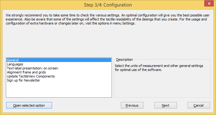
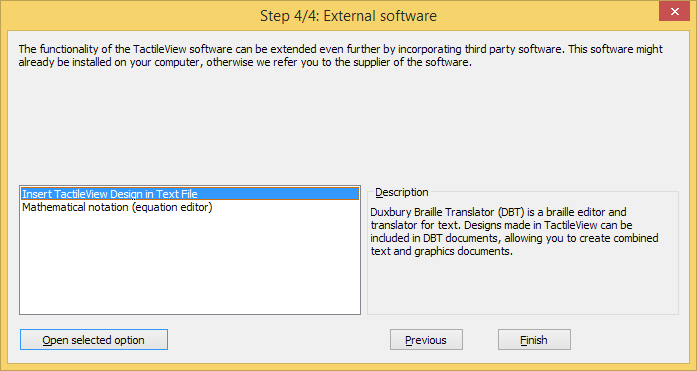
Once TactileView has been installed, you will be prompted with the Configuration wizard, which will guide you through registration and the most important settings for optimal use of the software. Each of the 4 steps in the configuration wizard are ‘Computer registration’, ‘Printer setup’, ‘Configuration’ and ‘External software’. In each step, there is a list with the essential settings. By selecting one from this list, you can read the description on the right. Click on ‘Open selected option’ to go to the selected settings dialog.
You can launch the Configuration wizard at any time later on by selecting it from the Help menu.
In the manual section Settings menu, you can find a more detailed list of all the settings menu option.
Configuration wizard: Introduction. This window gives an overview of the different steps in the configuration wizard. Click on ‘Start configuration wizard’ to proceed.
Configuration wizard step 1/4: Computer registration. In this step, you can register your software licence.
Configuration wizard step 2/4: Printer setup. This second step will help you to configure the steps required for printing your tactile designs.
Configuration wizard step 3/4: Configuration. All basic settings for operating the software are included in this third step.
Configuration wizard step 4/4: External software. This final step will help you to extend the functionality of TactileView with external software.
Once you have downloaded and installed the TactileView software, it will operate in demonstration mode at first. To run the software in full version, a software product code (SPC) is required. This SPC is provided by your dealer or has been sent by email after you purchased a software licence in the Thinkable shop.
The easiest and fastest method to register the software with your SPC is registration via the internet. However, TactileView also provides a registration option that does not require an internet connection; see Software registration via distributor (no internet access).
Each SPC is valid for one computer only. If you wish to use TactileView on multiple systems, you will need to purchase additional SPCs. For registration on multiple user accounts on the same computer, see Registration for multiple user accounts on single computer.
Software Product Code (SPC)
You will need to register the software using a Software product code (SPC) in order to get access to the complete set of software features. After purchasing a TactileView software licence, you will receive an SPC, either by email from the TactileView website, in a licence document from your dealer, etc. Make sure to store this code carefully, as you might need it later on for software updates or customer support.
Registration steps
Select ‘Registration via internet’ in step 1 of the Configuration wizard. Alternatively, choose ‘Computer registration’ from the Settings menu and make sure ‘Registration via internet’ is selected in the dialog that opens.
Enter your SPC, choose a User/company name and click on ‘Register now’.
Choose whether you wish to register the software for all users on the computer (requires administrator rights) or the current user only.
Enter and confirm the required contact details for customer support and optimal use of the software. You are now ready to start using the fully registered TactileView software.
This page collects the most common errors that can occur when embossing TactileView designs.
Index embossers – Paper length settings in Index firmware (Error 213)
When printing a TactileView design using Index V4 embossers with firmware version 1.5.3 or earlier, the embosser may prompt you with an audible ‘Error 213’ message. This is caused by an incorrect maximum number of lines per page in the firmware of the embosser. For example, the firmware uses 26 instead of the correct 27 lines for letter or 11 inch paper, or 28 instead of 29 lines for A4 paper.
When you select an Index V4 embosser in File > Print setup, you will be prompted with a ‘Paper length settings in Index firmware’ dialog that allows you to avoid or solve this error. You can also access this dialog via Help > Configuration wizard, then proceed to step 2.
To test whether you will encounter this error when embossing, first make sure to select the same paper size in TactileView and in the embosser. Next, click the button ‘Test printer for error 213’ and wait at least 10 seconds. If you hear no error message from the embosser, you do not have to take any further action and will not encounter the error when embossing a design. If you are prompted with error 213 however, press the ‘Off’ button on the embosser control panel and follow these steps:
1. Update the embosser firmware to firmware version 1.5.4 or higher. Check the Index website for availability and instructions.
3. If step 1 and 2 do not resolve the problem, you can temporarily reduce the number of lines per page in your TactileView designs. To do this, select ‘Reduce TactileView design height by 1 line per page’ in the ‘Paper length settings in Index firmware’ dialog. Important: if you execute step 1 or 2 later on, you will have to make sure the reduced design height option is no longer selected.
Index embossers – Error caused by mismatched paper size settings
When printing on an Index braille embosser, it is important to match both the design size and settings in the embosser with the size of paper you wish to print on. If these settings do not match each other, the embosser will report an error and the document will not be embossed correctly or will not be printed at all.
To solve this problem, check whether all paper size settings are set to the correct paper size. In TactileView, go to File > Print Setup and select the desired paper size.
Please read the Index Braille manual for your embosser for specific instructions on entering the right page formatting settings in your embosser model.
 Previous section
 Return to TactileView manual overview