Skip NavigationMenu

8.06 Saving grids as MyGrids

The example grids (empty grid paper as well as graphs) are called TVGrids. These examples can be modified to use them as the basis for your own graphs. Any grid can be added to this list by saving them as MyGrids. This allows you to easily store them for later use. You can find your saved MyGrids below the list of TVGrids in ‘Grids and graphs (advanced examples)’.

You can save a selected grid as MyGrid by selecting ‘Add to MyGrids’ from the properties toolbar or context menu. Enter agrid name as a reference, then click ‘Yes’ to save the grid.

‘Add to MyGrids’ icon: Add to MyGirds icon

Menu Graphs – Update MyGrids

If you wish to modify or remove any of the saved MyGrids, select ‘Update MyGrids’ from the Graphs menu and select one from the list.

To modify a MyGrid, select ‘Change properties’ to make the desired changes. After you have applied the changes, you can choose to save the modified grid as a new MyGrid by selecting ‘Add modified grid to MyGrids’ or overwrite the existing one by choosing ‘Replace changed grid in MyGrids’. You can also choose to delete one of the MyGrids from the list by selecting ‘Remove grid from MyGrids’.


Update MyGrids dialog

Figure 1. The ‘Update MyGrids’ dialog allows you to edit the list of saved graphs; click on the image to enlarge.

9.01 Inserting graphics in Duxbury Braille Translator (DBT)

When you have both TactileView 2.200 or higher, and Duxbury Braille Translator (DBT) 11.3 or higher installed, you will be able to insert a TactileView design into a text in DBT. This produces a document containing both text and graphics. You can choose to add a completely new design or use an existing file. The available space for the image will automatically be taken into account.

For TactileView version 2.250 or higher, an update is required for DBT to support high resolution graphics for Index V4 and V5 embossers. Select ‘Check for Updates’ from the Help menu in DBT to download and install this update.

If you do not have DBT installed yet, please visit their website.

1. Preparing DBT document
Launch DBT, create a new document and add the text in which you wish to insert tactile graphics. You can find more information on working in DBT, creating files and producing the correct braille translation on their website.

2. Inserting existing images
In order to insert a design, move the caret to the position in the DBT text where you want to insert an image. Select Layout > Picture > Add.., then select the desired TactileView design (.bpx file) and click Open. The tactile image is now inserted in the DBT text file. The small yellow logo in the upper right corner of the image indicates that the graphic was created in TactileView.

Adding a TactileView design in DBT: choose Layout > Picture > Add...

3. Image positioning
You can choose to insert an image either before or after translation of the braille document (ctrl+T). Either way, the amount of space needed on the page for the image is automatically taken into account. If the image is too large to fit on the current page, it will be placed at the top of the following page. Any empty white space around the edges of the TactileView design will be removed automatically for optimal use of space. For the best results, make sure that the same embosser and paper size are selected in TactileView and DBT. In TactileView, the red border indicates the available printable area for the selected combination of embosser and paper size.

Image inserted in DBT

4. Editing inserted images
If you wish to edit the inserted tactile graphics, simply double click on the image in DBT. This will launch the TactileView software, in which you can make any desired adjustments. Once you are satisfied, you can save the changes by clicking on the ‘Insert design in external text file’ icon in the top right corner of the canvas area, or select File > Insert design in external text file.

Icon for Insert design in external text file: Icon for returning to DBT

5. Removing images
You can remove inserted images by moving the caret position right after the image and pressing backspace, or delete with the caret just before the image.

6. Printing combined text and graphics files
An embosser that supports printing tactile graphics is required for printing the DBT file containing the images. In TactileView, you can see a preview of the graphic output of the selected embosser by selecting menu View > Design mode: dot view, or by viewing the print preview.

10.01 Accessibility with a screen reader (introduction)

The TactileView software is fully accessible with a screen reader. Due to its visual nature, creating a tactile design from scratch is very challenging for VIP users. However, many other aspects of the software can be used without the need for a sighted designer. This section will give an overview of the suitability for screen reader users of different aspects of TactileView.

Accessible menus

All menus and dialogs are accessible. Some of the menus are specially designed for screen reader users. Extra messages besides those of the screen reader itself are read out to provide additional explanations where appropriate.

Make sure the Settings menu Speech has been covered to make full use of these audible messages.

Mouse/freehand drawing vs. Menu driven design

To follow see the mouse on screen in the drawing area of the software is virtually impossible, even if the position of the mouse would be announced frequently. Keeping track of the created design is impossible with only speech and/or braille.

Existing images can be explored by analysing the colour composition, but how they are curved or the way how the lines intersect cannot be explored without printing the design. Therefore, creating or modifying ‘free-hand’ drawing is a step too far.

As an alternative, objects such as squares, circles and straight lines can be added to the design. Their positions are indicated by their properties (Ctrl+J).

Placing such an object can be done with the menu driven design menu (Ctrl+l).

Things that work really well for a screen reader

Below you will find some of the ways to create a tactile diagram while using a screen reader that work really well.

Creating digital designs by hand

Using the TactiPad drawing board would be a great alternative for creating tactile images as a VIP. Using this board, you can create a tactile drawing by hand. When combined with a camera, you can take a picture and digitally save your drawing or send it by mail. As a more advanced way of drawing, you can digitize your manual drawing using the TactileView Digital pen.

Download and Edit Design from Catalog (Portal menu)

You can use the catalog to find and download suitable tactile diagrams by selecting a category or searching for keywords in the title, textlabels or description.

Especially the alternate text that was given by the designer to describe the design can help to determine if this is the required design. The alternate text or description can be extended by any visitor of the catalog to make the description more detailed.

See also the section ‘Using the TactileView online catalog’.

Compose map (Portal menu)

To create a tactile map, choose ‘Compose map’ from the Portal menu. This will open a browser window with the website www.routetactile.com, on which you can create a map of any specified area. You can find a detailed description of all that is involved to create a tactile usable map in the Tactile Maps section.

Create mathematical graphs (Graphs menu)

With a screen reader, you can create a graph of any mathematical formula. You can either enter an equation to create your graph or start from one of the sample graphs in the software. See also the category Graphs and math in the TactileView manual.

Printing designs

You can also print designs on swellpaper or with a braille embosser by choosing ‘Print’ from the File menu. You can read more in the Printing section of the manual.

10.02 Settings – Speech

In most cases, screen reader users will have a speech output for general computer access. For specific applications, screen readers have functionality to monitor certain areas on the screen in order to provide speech output.

The TactileView software can also provide information that is helpful for a screen reader user from the status line of the software or info related to all the many tools and objects.

When the TactileView software is extended with the TactileView digital pen and either the TactileView ClickPad or the TactiPad drawing board, additional options for exploring audio-tactile diagrams or creating digital drawings become available.

The operation of these additional options greatly depends on using a screen reader. The speech settings are applied while using these extensions as well.

See also the sections in the category ‘Digital pen, TactiPad and ClickPad’

Language selection and Text-To-Speech (TTS)

Textlabels and messages are displayed in the language that was selected in the ‘Language’ dialog in the Settings menu.

For announcing these texts, a text to speech (TTS) synthesizer has to be selected. Microsoft supplies a few TTS engines with the Windows operating system. Extra TTS synthesisers can be installed from Eloquence, Nuance, L&H or other vendors.

Volume and rate

The volume and rate of spoken messages can be set to find a match with the volume and rate with the speech output of the screen reader. Use the ‘Speak’ button to test the selected voice, rate and volume.

Speak application messages (select checked)

The software can provide messages in addition to a screen reader. These messages contain status information about the drawing tools and properties of the objects. When you use TactileView with a screen reader, the option ‘Use text to speech for application messages and audio style’ should be checked.

Speak audio style or text label upon object selection (Select checked)

When an object gets the focus (is selected) the type of object and some properties are announced. For screen reader usage, ‘Speak audio style or text label upon object selection’ should be checked.

Text to speech for different languages

Some designs may contain texts in different languages, making the text to speech difficult to understand. If possible, it is best to use the TTS that matches the text label language.

For any languages in the list that show ‘not defined’, the default TTS synthesiser will be used. To apply a specific TTS synthesiser for a certain language, select the language from the list, then select the TTS you wish to use in the list below.

10.03 Drawing tools – Menu driven design (Ctrl+L)

TactileView is designed to allow the user to create and edit objects solely through the use of the menus, a feature referred to as ‘menu-driven design’. This method of creating graphics takes some practice, as you must decide where to place objects based on the distance of a specified critical point for each type of object away from the top and left edges of the design.

Menu-driven design may be used to edit existing graphics or to create new ones. This tutorial describes common functions for adding and editing objects in a drawing.

Adding objects

The drawing tools have been designed to use a coordinate-based drawing system. This means that each time you select a drawing tool, a dialog will appear that lets you specify the location in which the object will be inserted by inputting position and size information for that object.

Drawing straight lines

To draw a straight line, choose the ‘Draw Straight Line’ option from the Drawing tools menu. This will bring up a dialog allowing you to specify the position of the start and end points of the line you want to insert. Fill in the horizontal and vertical positions for the start and end points and enter the desired line length, then choose the ‘OK’ button to close the dialog and insert the line.

Drawing squares and rectangles

To draw a square or rectangle, select the ‘Draw Square-Rectangle’ option from the Drawing tools menu. This will bring up a dialog allowing you to specify the size and position of the square or rectangle you want to insert. Fill in the desired position of the upper left corner of the shape. To specify the size, first choose the Enlarge/reduce radio button if you want to insert square or the Stretch radio button if you want to insert a rectangle. Specify the width of the object. If you are inserting a square, you do not need to specify the height. If you are inserting a rectangle, enter the desired height of the object. Select the ‘OK’ button to close the dialog and insert the object.

Drawing circles and ovals

To draw a circle or oval, choose the ‘Draw Circle-Ellipse’ option from the Drawing tools menu. The dialog that comes up allows you to specify the size and position of the circle or oval you want to insert. Enter the position of the center of the circle. Next, choose either the Enlarge/reduce radio button to create a circle or the Stretch radio button to create an oval. Specify the width of your object. If you are inserting a circle, you do not need to enter the height. If you are inserting an oval, enter the desired height of the oval. Select the ‘OK’ button to close the dialog and insert the object into your file.

Drawing polygons

To insert a polygon, choose the ‘Draw Polygon’ item from the Drawing tools menu. A dialog appears, allowing you to enter the number of points you want in your polygon and define their positions. By default the polygon starts with three points. Select each point from the anchor points list and specify its location. The software calculates the angle from the previous point and the distance to the previous point for you. You can add more points by choosing the ‘Add anchor point’ button, and you can remove unnecessary points by choosing ‘Delete anchor point’. When you are finished, choose the ‘OK’ button to close the dialog and insert the shape.

NOTE: Points in the polygon can be added and deleted later when editing the shape with either the context menu options or the mouse.

Drawing triangles

To insert a triangle into your drawing, select the ‘Draw Triangle’ option from the Drawing Tools menu. The dialog that appears allows you to select the type of triangle you want to insert (right, isosceles, equilateral or scalene) and enter the positions of the points of the triangle. Select each point from the anchor points list and enter the desired position. The software calculates the length of each line segment touching the point, as well as the angle between them. When you are finished, choose OK to close the dialog and insert the triangle into your file.

Adding arows and other figures

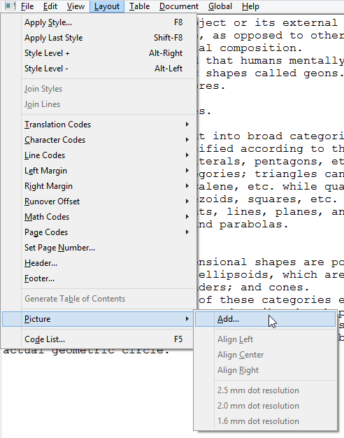
To add arrows or other commonly used shapes, choose ‘Add Figure’ from the Drawing tools menu. A dialog containing a list of available figure categories including arrows, electrical symbols and more appears. (NOTE: You can also add your own commonly used shapes as figures so that you can easily insert them into files. Please refer to the Adding Figures to the Figure Library tutorial for more information.) Browse through the categories and select a figure to add, then choose ‘OK’.

Next a size and position dialog appears, allowing you to specify the position of the figure in your drawing. Choose the Enlarge/reduce radio button if you want to lock the object’s height with respect to the width when choosing the size, or choose the Stretch radio button if you want to define the width and height separately. Choose the ‘OK’ button to close the dialog and insert the object into your file.

Drawing freehand lines

A true freehand line can be drawn accessibly using the digital pen with the software. However, you can draw a line or closed shape point by point with the menu-driven design by choosing the ‘Draw Freehand Line-Closed Shape’ option from the Drawing tools menu. The same dialog that appears for the ‘Draw Polygon’ function appears for drawing freehand lines, allowing you to enter the number of points you want in your line or shape and define their positions. By default the line or shape starts with four points. Select each point from the anchor points list and specify its location. The software calculates the angle from the previous point and the distance to the previous point for you. You can add more points by choosing the ‘Add anchor point’ button, and you can remove unnecessary points by choosing ‘Delete anchor point’. When you are finished, choose the ‘OK’ button to close the dialog and insert the shape.

NOTE: Points in the line or shape can be added and deleted later when editing it.

Text labels

You may add text format labels to a file at any time. There are several formats of labels available for use in TactileView. The most commonly used type of label in TactileView is referred to simply as a ‘text label’. Text labels may be entered in plain text and be automatically translated to braille when they appear in the document, or they may be entered directly in braille through six-key input.

In addition to text labels, TactileView offers the option to add mammoth braille labels or print character labels that will be embossed as raised text.

NOTE: Labels may only be edited according to the input method used to create them. For example, a text label entered via braille (six-key) input may only be edited using six-key, and a raised print character label may only be edited as a raised print character label. Labels can’t be converted from one type of label to another.

Adding text labels

The most commonly used type of label in TactileView is referred to simply as a ‘text label’. Text labels may be entered in plain text, and then they are automatically translated to braille when they appear in the document.

When using menu-driven design, text labels can be added either by choosing ‘Add Text Label’ from the Drawing Tools menu of the software, or by opening the List of Objects (Ctrl+L), choosing the ‘Add Text Label or Object’ button and selecting ‘Add Text Label’ from the list of options.

A dialog will appear, allowing you to enter the text for your label, select the braille table to use for translation and input position information.

Enter the text you want to use in your label into the Contents box. Select the braille table to use for translation from the Select Braille Table for this Label combo box.

Enter the location for the text label by editing in the Distance to Left Edge and Distance to Top Edge fields. You can also control the width of the text label by specifying the maximum number of characters you’d like it to have before the text wraps to the next line. Choose ‘OK’ to close the dialog and insert the label.

Adding text labels through six-key entry

Currently this option is only available accessibly through the use of the digital pen. Please refer to the Accessible Drawing Using the Digital Pen tutorial.

Adding mammoth braille labels

When using menu-driven design, mammoth braille labels can be added either by choosing ‘Draw Mammoth Braille’ from the Drawing Tools menu of the software, or by opening the List of Objects (Ctrl+L), choosing the ‘Add Text Label or Object’ button and selecting ‘Draw Mammoth Braille’ from the list of options. In the dialog that appears, enter the text you wish to appear in mammoth braille and specify the position in which it should be inserted. Choose ‘OK’ to close the dialog and insert the mammoth braille label into your file.

Adding raised print character labels

When using menu-driven design, raised print character labels can be added either by choosing Draw Letters and Digits from the Drawing Tools menu of the software, or by opening the List of Objects (Ctrl+L), choosing the Add Text Label or Object button and selecting Draw Letters and Digits from the list of options. This launches a dialog that allows you to enter the text you wish to appear as print characters and specify its location in the drawing. Set the options as desired and choose ‘OK’ to close the dialog and insert the label into your file.

Editing objects

Selecting objects

To select an object in the current drawing, open the List of Objects dialog either by choosing Menu Driven Design from the Drawing Tools menu (Alt+T, then M) or with the hotkey Ctrl+L. The List of Objects dialog shows the complete list of drawing objects in the current drawing by object type and gives identifying information about each object. To select an object, arrow through the list until you locate the object you want to work with.

If, after selecting an object, you select the OK button on the List of Objects dialog, the dialog closes and the object you chose is selected. However, most common editing functions may also be performed directly from the List of Objects dialog, and this is the recommended method when using menu-driven design.

Copying, pasting and deleting objects

To copy an object, first press Ctrl+L to bring up the List of Objects dialog. Locate the object you wish to copy, choose the Open Context Menu button and select Copy. The object has now been copied to the clipboard.

To paste an object from the clipboard, choose Paste from the Edit menu (Alt+E, P) or press Ctrl+V. This pastes the object centered at the upper left corner of the design.

To delete an object, first press Ctrl+L to bring up the List of Objects dialog. Locate the object you wish to delete, choose the Open Context Menu button and select Delete.

Moving and resizing objects

Select the object you wish to move or resize from the List of Objects dialog and choose the Open Context Menu button. The context menu is slightly different depending on what object type is selected, but the position dialog can always be accessed through the first context menu item, which will be Size and Position, Text and Position or Positions of anchor points. Select this item to bring up the same dialog used to create the object initially, in which you can enter new locations for critical points in the object if you wish to move the object, or enter new height and width settings for objects if you wish to resize them.

You can also center an object horizontally in the drawing by selecting it, choosing the Open Context Menu button and choosing Center. This will only automatically center the object horizontally; it will keep the same vertical position on the page.

Rotating objects

Select the object you wish to rotate from the List of Objects dialog, choose the Open Context Menu button and select Rotation. On the dialog that appears, enter the desired angle of rotation in degrees and choose OK to rotate the object.

Changing object line properties

Select the object you wish to edit from the List of Objects dialog, choose the Open Context Menu button and select Line Style. This opens a dialog from which you can set the line properties for the object, including the line pattern (solid or dashed) and thickness. The drop-down list for the line pattern describes the number of pixels of black + the number of pixels of white that make up the line. For example, 2+2 means that the line will have two pixels of black followed by two pixels of white, while 5+3 will have five pixels of black followed by three pixels of white (so that the line is a pattern of longer black lines with shorter white spaces in between). Once you select the line patter, choose the thickness of the line in pixels. Choose OK to apply your changes to the object and close the dialog.

Changing object fill properties

Select the object you wish to edit from the List of Objects dialog, choose the Open Context Menu button and select Fill Style. This opens a dialog from which you can set the fill properties, including selecting a fill texture, scaling the size of the fill tiles and rotating the texture within the object.

If you would like to add a fill texture to your object, select the Use Texture Fill radio button. Choose the Change Texture button to bring up a dialog containing a list of textures that can be used. Select a texture from the list of options and choose OK. Use the Tile Size in Pixels edit box to scale the texture larger or smaller. You can also rotate the texture using the Texture Rotation Angle edit box. When you are finished making changes, choose OK to apply the fill to your object.

Adding audio labels

Audio labels are a great way to add more information to a drawing without having to make it larger to accommodate more text or graphical information. The audio information is accessed by using the file in explore mode, either on screen with a mouse or on a tactile copy on the Clickpad or Tactipad with the digital pen. For more information on explore mode, please refer to the Using Explore Mode and Using the Pen in Explore Mode with the Clickpad or Tactipad tutorials.

Audio labels can be added to any type of drawing object in TactileView, and to mammoth braille or raised print character labels. Audio labels may not be added to text labels, because text labels are automatically voiced by text-to-speech when the file is used in explore mode.

Adding an audio label to be voiced by text-to-speech

Select the object you wish to add an audio label to from the List of Objects dialog, choose the Open Context Menu button and choose Audio Style. This will launch an audio label dialog, the top section of which allows you to specify the text to be voiced by synthetic speech from one of several sources.

In the “Text or document in synthetic speech (TTS) section of the dialog, the default choice is the Self Defined Text radio button, which allows you to type the text you want voiced into the text field on the dialog. If you have text saved in a text file that you would like voiced instead, you can select the Text from Local File radio button, then choose the Browse button to browse to and select your text file. Once you have specified the text, you can check how the label will sound by selecting the Test Audio Label button. When you are finished making changes, choose the OK button to close the dialog and apply the audio label.

Attaching an existing sound file to an object

You can also attach an existing sound file to an object to have it played when the object is clicked while the file is in explore mode. To do this, select the object you wish to add an audio label to from the List of Objects dialog, choose the Open Context Menu button and choose Audio Style. This will launch an audio label dialog, the bottom section of which allows you to specify a sound file to play when the object is clicked in explore mode.

In the “Insert sound sample from” section of the dialog, the default choice is the Local File radio button, which is the one needed to attach a sound file to the object as a label. Select the Browse URL button, locate the sound file you would like to use on your computer and select it. The file path to the sound file will now appear in the text field below the sound file type selection radio buttons. You can check how the audio label will sound by selecting the Test Audio Label button. When you are finished making changes, choose the OK button to close the dialog and apply the audio label.

NOTE: If you have both a text-to-speech audio label and a sound file audio label attached to the same object, the text-to-speech will be voiced first and the sound file will play after it.

Recording an audio label from a microphone

Audio labels recorded from a microphone are played when the object is clicked with the mouse or digital pen while using the file in explore mode. Recorded labels are played after any text-to-speech labels are voiced.

Before recording, you will need to ensure that you have a microphone connected to your computer. When you have connected a microphone to your computer, you can record an audio label for an object by selecting the object from the List of Objects dialog, choosing the Open Context Menu button and selecting Record Microphone. An Audio Recording dialog appears, allowing you to select the microphone from which you wish to record, the format in which to record the sound, the location in which to store the recording and the volume percentage at which to record. To begin recording, choose the Start Recording button. To stop recording, press enter. To play back your recording, choose the Play Recording button. If you wish to re-record your audio label, just repeat the recording process. Only the most recent recording will be attached as the audio label for the file.

NOTE: Each object may only have one text-to-speech audio label and one recorded or sound file audio label associated with it. If you record an audio label for an object, it will replace any existing sound file you may have associated with that object previously.

Editing an existing audio label

You may edit any type of audio label by repeating the steps used to create the audio label.

10.04 Browsing and selecting objects (Tab or Shift+Tab)

All objects that have been placed in the design with one of the drawing tools are grouped in the objects list (Ctrl+M). From this list, the respective context menus can be opened to change the properties of the object.

You can select an object or text label in the design by choosing it from this list, then pressing ‘OK’.

Cycle through text labels and objects with Tab or Shift+Tab

To conveniently cycle through the objects and text labels that are present in the design, use Tab (cycle forward) or Shift+Tab (cycle backwards). One by one, the objects and text labels will get the focus (will be selected). The name and position of the object or label will be announced.

This way you can cycle from top to bottom through the design. If any objects are horizontally aligned, the objects further to the left will come first.

Use Ctrl+K or the enter key to open the context menu if you wish to make any changes to the object.

10.05 View – Context menu (Ctrl+K or Enter)

Any objects that were placed in the design can be edited later on. Opening the context menu of a selected object or drawing tool gives access to all the properties that can be changed. Read ‘Browsing and selecting objects‘ to find out how to make your object selection.

View – Open context menu (Ctrl+K or Enter)

Once you have selected an object in the design, you can open the context menu by choosing ‘Context menu’ from the View menu. Alternatively, you can press Ctrl+K or the Enter key as a shortcut to open the context menu.

Open context menu via Object list (Ctrl+M)

The object list shows all object that are present in the design. Choose ‘Open context menu’ in this object list dialog. The respective context menu will open, in which you will find all options to edit the properties of the selected object.

See also the section Editing object properties.

10.06 View – Show properties (Ctrl+J)

When an object is selected in the design, it can be very useful for screen reader users to get a quick list of all the properties. To can select an object in your design, choose either ‘Menu driven design’ from the Drawing tools menu (Ctrl+L), or ‘List of objects’ from the View menu (Ctrl+M). In either list, select the object and press ‘OK’. The object now has the selection. The properties list of the selected object can be opened by selecting ‘Show properties’ in the View menu, or by pressing Ctrl+J.

The list of properties include aspects such as size, position in the design, etc. Use the button ‘Speak properties’ to hear the properties in a spoken message. If you wish to make any changes to the object, choose ‘Open context menu’.

11.01 Introduction and preparation steps

Introduction

TactileView tactile graphics suite for VIP users.

In the sections in this category we elaborate on using the combination of all components of the TactileView tactile graphics suite by a visually impaired person (VIP). The assumption is that the user is using a screen reader with speech and/or braille output.

The addition of the TactileView software with a digital pen and either a TactiPad drawing board or a TactileView ClickPad brings new possibilities with respect to tactile diagrams: creating digital designs by a VIP and exploring audio tactile diagrams with more than just tactile information.

Skill level

Please be informed that using the TactileView digital pen requires a high level of experience. We strongly suggest to follow the steps below in order to develop the necessary skills before starting to use the product combinations with the digital pen. By following the steps, you will not be discouraged by the learning curve that is involved.

You can read more about the aspects of using the digital pen in the ‘Considerations’ section.

Preparation steps

As the skill level of using the digital pen to operate TactileView and draw on the TactiPad is relatively high, it is very useful to build up a good comprehension of the different aspects separately before using them together. The following steps will give an overview of the best approach to master using the digital pen as a VIP user. By breaking it down into individual steps, we encourage you to explore the increasing possibilities that the combinations of the products in the Tactile graphics suite

  1. Basic understanding – TactileView tactile graphics
  2. 1.1 It is a big advantage when you already have a good understanding for tactile diagrams in general. Therefore we suggest to first to download and print pre-made designs from the TactileView catalog, compose a map with RouteTactile or print graphs based on any equation. This allows you to ‘get a feeling’ for exploring a tactile diagram with your fingertips.

    1.2 Make sure you can operate the software with a screen reader. Get familiar with navigating through the menus and dialogs in the software using a screen reader and practise operating the software with by downloading and printing designs from catalog.

  3. Basic understanding – TactiPad
  4. 2.1 Practise creating a complete tactile drawing by hand on the TactiPad with a regular pen. You could start with a basic sketch to get a feeling for drawing by hand. Make sure to get familiar with using the pen and drawing tools to create a tactile image.

    You can use the ‘TactiPad user manual’ as a guide.

  5. Preparing the hardware – Digital pen and TactiPad
  6. 3.1 Place the batteries in the digital pen.

    3.2 Place the pen’s receiver in its holder and with its magnets position it on the side of the TactiPad.

    3.3 Connect the USB cable to the receiver and your computer.

    See the ‘Digital pen user manual’ for all details on steps 3.1 to 3.3.

  7. Preparing the software
  8. 4.1 Cover the different parts of the dialog ‘TactileView digital pen’ in menu Settings.

    4.2 In the ‘TactileView digital pen’ settings dialog, test the connection of the digital pen.

    4.3 How and where to place the receiver relative to the TactiPad or ClickPad and orientation (landscape, portrait).

    4.4 Calibrate the pen within the space for the TactiPad or ClickPad

    Read ” for a complete guide through steps 4.1 to 4.4.

  9. Understanding the various actions and responses of the pen
  10. 5.1 Make sure you know where to point and how to click to navigate through the software using the digital pen. Learn how to access context menus and select the menu options.

    5.2 Make yourself familiar with the sounds and messages that signify over 20 pen functions. Be aware of the state of the digital pen at all times (sounds and messages; the pen can have over 20 different functions; this is a sub set of the functions that are available in the menus)

    5.3 Understand how the surface (dimensions) of the TactiPad relates to the size of the drawing area on the screen and vice versa.

    5.4 Know when to use the computer keyboard or the menus that are accessible with the pen. There is no need to use the computer keyboard when operating the software with the pen, except for entering texts.

  11. Start creating digital tactile drawings
  12. 6.1 Start by creating basic drawings with a limited number of objects using ‘Menu driven design’. Creating or modifying an image by a VIP can only be done with a good comprehension of the tools and their effects on an image. Using the TactileView digital pen requires that you understand the tools from the ‘Drawing tools’ menu and are able to investigate the screen from the ‘List of objects’ in the View menu. Explore what the different objects will look like when they are printed.

    In general, you do not really use the tools such as ruler, protractor and triangle to create an exact drawing, but your drawing is based on the status information (object type, position etc.) in speech. When drawing objects with the TactileView digital pen, you are not physically drawing the lines of the objects on the TactiPad, but you are working with tactile reference points to mark the various objects that you want to add to the digital design. The various objects are added to the design and positioned aligned to these reference markers.