Skip NavigationMenu

6.12 Draw letters and digits

NOTE: Keep in mind that this drawing tool is not intended to present texts in braille, but as a tool to show the contours and shapes of visual text characters. Various font types and font sizes can be used to illustrate font attributes such as serif, italic or bold.

To draw a text in the design, select the ‘Draw letters and digits’ icon from the left vertical toolbar. Click in the design where you wish to place the large text. Enter the contents in the dialog that appears and click ‘OK’. You can use the purple markers to resize the text, which should be large enough for tactile use to distinguish the characters.

‘Draw letters and digits’ icon: Draw letters and digits icon

Large blue letters drawn using 'Draw letters and digits'

Figure 1. Add large text to your design with ‘Draw letters and digits’

Large blue texts with different font sizes

Figure 2. Font type and size for letters and digits can be adjusted.

‘Font type and size’ icon: Font type and size icon

6.10 Import (image from file, svg and figure)

There are several ways in which you can add an image to your TactileView design.

  • When you regularly use the same icons or images, ‘Add figure’
  • Saved SVG image files can be added with ‘Import SVG’
  • Saved jpg, png or other bitmap images are added with ‘Import image from file’

These import functions are activated by selecting ‘Import’ from the left vertical toolbar, then selecting the specific tool from the right vertical toolbar.

‘Import’ icon: Import icon
‘Import SVG’ icon: Import SVG icon
‘Import image from file’ icon: Import image from file icon

Add figure

Figures are image objects that are useful when you wish to reuse certain symbols and shapes (such as arrows, electrical symbols, more abstract shapes, etc) in multiple documents. Once you have activated the ‘Add figure’ drawing tool, a dialog will appear in which you can You can browse through the different categories and select the figure you wish to use.

Once you click ‘OK’ to confirm your choice, the figure will be visible at the position of your mouse. Click anywhere to place the figure as an object in your design.If the object is not the desired size when it appears in the design area, you can edit it by dragging the purple markers on the corners and sides.

Settings – personal figures folder
TactileView contains a set standard icons, symbols and other figures. By selecting ‘Figures’ from the Settings menu, you can also select additional folders that contain your personal sets image files that you can use as figures.

Select area – Save as figure
When using the Select area tool, you can select ‘Save as figure’ from the context menu or properties toolbar. This saves the selected area as a figure that can later be reused and will include the bitmap layer as well as any objects within the selection. Keep in mind that text labels are not included in the figure. See the manual section ‘Select area‘ for more information.

Add figure dialog

Figure 1. From the dialog, choose one of the figures to insert in your design; click on the image to enlarge.

Import SVG and Import image from file

Vector graphics (svg files) as well as bitmap image files (jpg, png, bmp, etc.) can be imported in your design by selecting ‘Import SVG’ or ‘Import image from file’. In the dialog that opens, browse to the image file you wish to use and double click or select ‘Open’ to confirm the selection. Next, click anywhere to place the image as an object in the design. You can use the purple markers on the corners in case the image needs to be resized.

10.04 Browsing and selecting objects (Tab or Shift+Tab)

All objects that have been placed in the design with one of the drawing tools are grouped in the objects list (Ctrl+M). From this list, the respective context menus can be opened to change the properties of the object.

You can select an object or text label in the design by choosing it from this list, then pressing ‘OK’.

Cycle through text labels and objects with Tab or Shift+Tab

To conveniently cycle through the objects and text labels that are present in the design, use Tab (cycle forward) or Shift+Tab (cycle backwards). One by one, the objects and text labels will get the focus (will be selected). The name and position of the object or label will be announced.

This way you can cycle from top to bottom through the design. If any objects are horizontally aligned, the objects further to the left will come first.

Use Ctrl+K or the enter key to open the context menu if you wish to make any changes to the object.

10.02 Settings – Speech

In most cases, screen reader users will have a speech output for general computer access. For specific applications, screen readers have functionality to monitor certain areas on the screen in order to provide speech output.

The TactileView software can also provide information that is helpful for a screen reader user from the status line of the software or info related to all the many tools and objects.

When the TactileView software is extended with the TactileView digital pen and either the TactileView ClickPad or the TactiPad drawing board, additional options for exploring audio-tactile diagrams or creating digital drawings become available.

The operation of these additional options greatly depends on using a screen reader. The speech settings are applied while using these extensions as well.

See also the sections in the category ‘Digital pen, TactiPad and ClickPad’

Language selection and Text-To-Speech (TTS)

Textlabels and messages are displayed in the language that was selected in the ‘Language’ dialog in the Settings menu.

For announcing these texts, a text to speech (TTS) synthesizer has to be selected. Microsoft supplies a few TTS engines with the Windows operating system. Extra TTS synthesisers can be installed from Eloquence, Nuance, L&H or other vendors.

Volume and rate

The volume and rate of spoken messages can be set to find a match with the volume and rate with the speech output of the screen reader. Use the ‘Speak’ button to test the selected voice, rate and volume.

Speak application messages (select checked)

The software can provide messages in addition to a screen reader. These messages contain status information about the drawing tools and properties of the objects. When you use TactileView with a screen reader, the option ‘Use text to speech for application messages and audio style’ should be checked.

Speak audio style or text label upon object selection (Select checked)

When an object gets the focus (is selected) the type of object and some properties are announced. For screen reader usage, ‘Speak audio style or text label upon object selection’ should be checked.

Text to speech for different languages

Some designs may contain texts in different languages, making the text to speech difficult to understand. If possible, it is best to use the TTS that matches the text label language.

For any languages in the list that show ‘not defined’, the default TTS synthesiser will be used. To apply a specific TTS synthesiser for a certain language, select the language from the list, then select the TTS you wish to use in the list below.

10.06 View – Show properties (Ctrl+J)

When an object is selected in the design, it can be very useful for screen reader users to get a quick list of all the properties. To can select an object in your design, choose either ‘Menu driven design’ from the Drawing tools menu (Ctrl+L), or ‘List of objects’ from the View menu (Ctrl+M). In either list, select the object and press ‘OK’. The object now has the selection. The properties list of the selected object can be opened by selecting ‘Show properties’ in the View menu, or by pressing Ctrl+J.

The list of properties include aspects such as size, position in the design, etc. Use the button ‘Speak properties’ to hear the properties in a spoken message. If you wish to make any changes to the object, choose ‘Open context menu’.

10.05 View – Context menu (Ctrl+K or Enter)

Any objects that were placed in the design can be edited later on. Opening the context menu of a selected object or drawing tool gives access to all the properties that can be changed. Read ‘Browsing and selecting objects‘ to find out how to make your object selection.

View – Open context menu (Ctrl+K or Enter)

Once you have selected an object in the design, you can open the context menu by choosing ‘Context menu’ from the View menu. Alternatively, you can press Ctrl+K or the Enter key as a shortcut to open the context menu.

Open context menu via Object list (Ctrl+M)

The object list shows all object that are present in the design. Choose ‘Open context menu’ in this object list dialog. The respective context menu will open, in which you will find all options to edit the properties of the selected object.

See also the section Editing object properties.

10.01 Accessibility with a screen reader (introduction)

The TactileView software is fully accessible with a screen reader. Due to its visual nature, creating a tactile design from scratch is very challenging for VIP users. However, many other aspects of the software can be used without the need for a sighted designer. This section will give an overview of the suitability for screen reader users of different aspects of TactileView.

Accessible menus

All menus and dialogs are accessible. Some of the menus are specially designed for screen reader users. Extra messages besides those of the screen reader itself are read out to provide additional explanations where appropriate.

Make sure the Settings menu Speech has been covered to make full use of these audible messages.

Mouse/freehand drawing vs. Menu driven design

To follow see the mouse on screen in the drawing area of the software is virtually impossible, even if the position of the mouse would be announced frequently. Keeping track of the created design is impossible with only speech and/or braille.

Existing images can be explored by analysing the colour composition, but how they are curved or the way how the lines intersect cannot be explored without printing the design. Therefore, creating or modifying ‘free-hand’ drawing is a step too far.

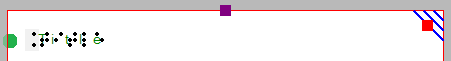
As an alternative, objects such as squares, circles and straight lines can be added to the design. Their positions are indicated by their properties (Ctrl+J).

Placing such an object can be done with the menu driven design menu (Ctrl+l).

Things that work really well for a screen reader

Below you will find some of the ways to create a tactile diagram while using a screen reader that work really well.

Creating digital designs by hand

Using the TactiPad drawing board would be a great alternative for creating tactile images as a VIP. Using this board, you can create a tactile drawing by hand. When combined with a camera, you can take a picture and digitally save your drawing or send it by mail. As a more advanced way of drawing, you can digitize your manual drawing using the TactileView Digital pen.

Download and Edit Design from Catalog (Portal menu)

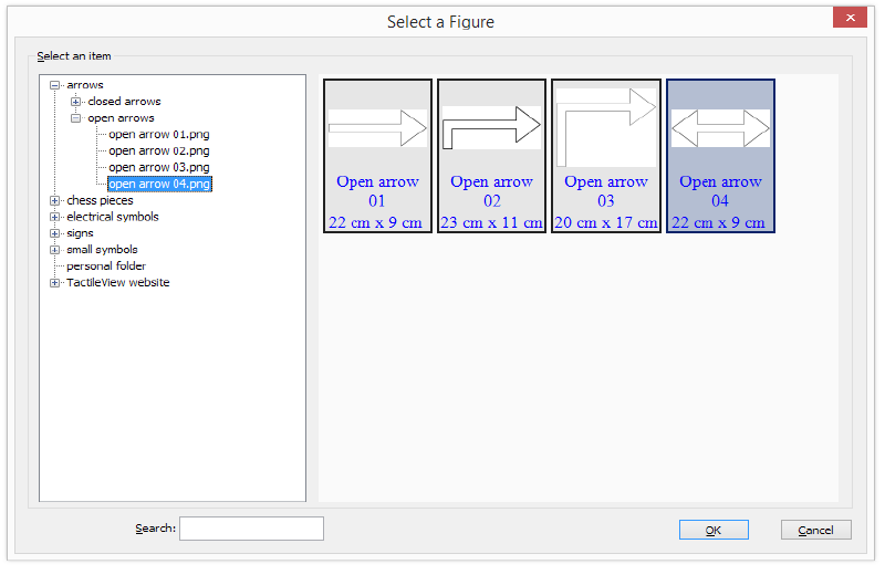
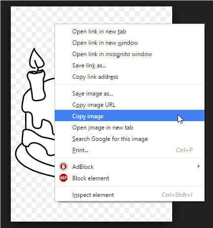
You can use the catalog to find and download suitable tactile diagrams by selecting a category or searching for keywords in the title, textlabels or description.

Especially the alternate text that was given by the designer to describe the design can help to determine if this is the required design. The alternate text or description can be extended by any visitor of the catalog to make the description more detailed.

See also the section ‘Using the TactileView online catalog’.

Compose map (Portal menu)

To create a tactile map, choose ‘Compose map’ from the Portal menu. This will open a browser window with the website www.routetactile.com, on which you can create a map of any specified area. You can find a detailed description of all that is involved to create a tactile usable map in the Tactile Maps section.

Create mathematical graphs (Graphs menu)

With a screen reader, you can create a graph of any mathematical formula. You can either enter an equation to create your graph or start from one of the sample graphs in the software. See also the category Graphs and math in the TactileView manual.

Printing designs

You can also print designs on swellpaper or with a braille embosser by choosing ‘Print’ from the File menu. You can read more in the Printing section of the manual.

4.03 Importing images from the internet

Images from the internet often form a great source for a tactile image. The amount of different subjects that can be portrayed is virtually endless. However, selecting the right material from this vast resource can both improve the tactile quality and minimize the effort needed to convert the image into a tactile diagram.

Understanding which image works best

Virtually any image can be used as a basis for a tactile diagram, but some are more suitable than others. For example, some images are harder to understand when they converted to a tactile image. In general, a higher level of detail will result in a more difficult tactile diagram. Concepts such as shadows or three-dimensional perspective can be very hard to understand for a blind reader.

The second consideration is the amount of effort it takes to convert the image to a tactually usable design. Of course it depends greatly on the type of contents you wish to include in the image, but generally ‘less is more’: a simpler image takes less time to convert than a more detailed one.

An image needs to have enough features that can be understood by touch. This means that images often need to be simplified by isolating individual lines from the In most cases, line images are preferred as a basis for a design.

Two different birthday cards: a complex one on the left, a less detailed one on the right

Figure 1. The image on the right has less fine detail and is less complex, making a tactile version easier to read and taking less effort to edit than the image on the left.


Make clever use Google image search

Using Google, you can search for images that match any keywords that you enter. In most cases this will give thousands of results, so in many cases you will need to refine your search criteria. You could try searching for a synonym or closely related word (e.g. ‘trees’ or ‘woods’ instead of ‘forest’). If you speak multiple languages it can be helpful to search for the same concept in another language.

Google also provides some tools to refine the type of image you are looking for. You can find these by clicking on the ‘Search tools’ button. These allow you to make some useful selections for finding the right material for tactile use. The most important selections for tactile use are:

– Size: larger images are generally better than smaller images, since they provide a better image quality in which more detail is retained when enlarged. You can also select ‘Show sizes’ under ‘More tools’ to get a quick overview of the image sizes.

– Type: refine the type of images that are presented. ‘Line drawing’ or ‘Clip art’ both are highly suitable as a basis for a tactile image, as they are often already simplified into individual lines and will be closer to what is required for a tactile image. We always advise to check first if these types of images are available to minimize the amount of effort it takes to create a tactile image.

The other search tools, such as colour and time can be used to further refine your search results. Appropriate usage rights can be selected if it concerns reproduction.

Photo of a real birthday cake on the left, line drawing of a birthday cake on the right

Figure 2. By making use of the Search Tools, you can select line drawings (right) instead of more complicated images, such as the photo on the left; the line drawing is much easier to read and edit.

Placing the image in your TactileView design

Once you have found a suitable image, right click on it to open the context menu, then select ‘Copy image’. This will copy the image onto your clipboard. In TactileView, press Ctrl+V to paste the image in your design. This will place the image in the design area at the position of you mouse. You can also right click in an empty area of the design, then select ‘Paste’ to place the image on the position of the click. Or you can select ‘Paste’ from the Edit menu or click the ‘Paste’ icon in the top horizontal toolbar, which will place the image in the top left corner of the design.

If you have saved an image on your computer, you can choose ‘Import’ from the drawing tools icon bar, then select ‘Import SVG’ for svg images or ‘Import image from file’ for bitmap image (.jpg, .png, …), or select ‘Import image from file’ from the File menu. Next, click in the design where you wish to insert the image.

You can always resize or move the image to the required position in the design. Use the retouching tools (pen and eraser), a combination of the filters from the drawing tools toolbar or the Filters menu, or any of the other drawing tools to make the required adjustments to make the inserted image suitable for tactile use.

2015-10-08_11-55-25

3.02 After launching the software

In this section you can find a first introduction to some of the first software functions you will come across when you create a tactile design.

First impression

After launching the software, the red border is showing the current paper size and orientation.

The word ‘Title’ can be found in the top left corner. This is to make you aware of the importance of a title in your design, which will help the reader to understand the content of the diagram at hand.

When you open a new design, you will see a tactile marker in the upper right corner. This so-called right-up marker helps a blind reader to easily find out the paper orientation without having to explore its contents first. This the position of the right-up marker is always in the top right corner, independent of landscape or portrait orientation. On screen, the marker is shown as three blue lines at an angle of 45 degrees.

For most designs we advise you to include the right-up marker for ease of use. However, by clicking on the marker it can be turned off, which for example can be used if you want to print multiple designs in a bundle and bind them. A red marker will remain which can be activated to switch the marker on again.

Red paper border, title and right-up marker

Figure 1. The top of the design shows the title text label, right-up marker and red border for paper size and orientation.

Design orientation: landscape or portrait designs

Choosing the right paper orientation for your design allows you to make optimal use of the available space on the paper. This way the image can be presented as large as possible in order to retain smaller details. You can change the paper orientation by clicking on the ‘Change the orientation to landscape/portrait’ icon in the design toolbar (second vertical toolbar when nothing is selected). You can also find this option in the Design menu.

It is important to know that changing the paper orientation will not adjust the size of the image! This ensures that the tactile quality of the image is maintained. However, you might need to adjust the width and/or height manually to fit the new paper orientation by dragging the markers around the design.

‘Change the orientation to landscape’ icon: Change the orientation to landscape

‘Change the orientation to portrait’ icon: Change the orientation to portrait

Portrait to landscape orientation

When you start with a design with a tree in portrait mode and you decide you want to have it in landscape, you can change the paper orientation. The size of the white design area that contains the tree will stay the same.

It is likely that the lower part of your design will now be outside the red border and that you have two sheets of paper instead of one. Even though you could have a design spread over multiple sheets, chances are you would want to reduce the design size to fit a single sheet of paper. You can use the blue marker in the lower right corner to make the height of the tree fit. Please note that your tree has become smaller, so make sure any smaller details are still adequate for tactile use. Next, use the purple marker in the middle of the right side of your design to add paper to span the width of the paper.

Landscape to portrait orientation

The other way around, you might start with a tree that spans the height of a design in landscape orientation, but decide you want it to be in portrait to make better use of the length of the paper. In that case, you could increase the size of the image by using the blue marker in the lower right corner. You can use the purple markers in the middle of the two sides of the white area to trim any empty space left and right of the tree.

For more information, see section ‘Paper size vs. design size‘.

Line view and Dot view

To get you familiar as soon as possible with the effect of creating designs for braille embossers, you can view the design on screen as it will be embossed in dots.

For good visibility you can use the line view mode for the drawing. When you switch to dot view, all lines will be converted to individual dots, just as your braille embosser will do.

You can read more in the section ‘Design mode: dot view/line view‘.

Difference between dot view and line view
Figure 2. A circle shown in line view (left) or dot view (right) shows the graphic capabilities of the selected embosser.