Skip NavigationMenu

TactileView version 1.950 – release notes

The software has been tested and prepared for Windows 8. The support for a touchscreen, one of the elements of the Windows 8 interface, is implemented.
Drawing objects with your finger or zoom in/out (pinching) or rotating objects has never been so easy.

The TactileView drivers have been prepared for 64-bit Windows. Especially the combination with the Index embossers Version 4, has gone through an extensive testing procedure. See the ‘Index’ section below.

File menu

In the file menu the option ‘Import SVG’ is added. This allows you to import files with file format SVG. To clarify: The ‘Open’ option will open files in TactileView format (BPX), JPG, PNG, TIF and GIF.
The File menu option ‘Print Multiple Documents’ has been changed to select and print a list of designs more easily. This can be done by selecting multiple designs from a folder or by creating firstly a .txt-file with the file names.
When files in the print list could not be found (either due to a misspelled file name or wrong document location), the list can be changed by selecting a replacing file and saving the corrected print list.

Settings menu

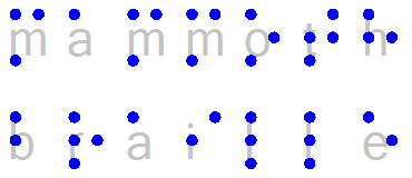
In the Settings menu, the ‘Braille Tables’ option has been extended with the inclusion of the LibLouis braille translation. This is an open source system for the use of various braille tables in different languages, including contracted braille. With the incorporation of this system, TactileView can now apply multiple braille tables in the same document.
Settings – Braille tables: First of all, create your own list of braille tables that you want to apply when creating or editing a design. As you enter a new text label or edit an existing one, you can then select a braille table that you like to apply to the selected text label.
In order to get an overview of the different braille tables that are applied to present the text labels in the current document, the function ‘Braille table overview’ in the toolbar or context menu of the design can be selected. This will present the names of the braille tables in a specific colour. The respective labels in the design will have markers with the corresponding colour.
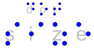
The presentation of the textlabels in normal font is based on the number of braille characters. In other words, when a textlabel has braille contractions, a smaller fonttype is used in order to avoid overlapping in the design.

Graphs menu

A new option has been added to the Graphs menu: ‘Functions and Formulas. Here you can find a list of all the mathematical functions and constants that can be used in a formula.
Also a list of sample formulas is available in this menu option. All settings can be changed to create the formula that suits your needs. This option uses the same underlying technique as in the Grids and Graphs menu. This option presents a list of Grids and Graphs, based on a number of sample formulas.
The grids an formula list contains quite a number of settings to be able to create a tactile usable graph.
The names of the grids are localized.

Index printers

Although Index Braille AB provides drivers for its printers, you should install a TactileView driver.
After you have installed the standard driver from Index, the TactileView printer driver can be installed via the TactileView program, menu option File – Install Braille printer.
Depending on your printer model:
For Index printer model V4 select the type: Index Printer (V4 0.5 mm).
The printer port must be set to the same value as is selected by the Index driver.
Make sure you have the latest Index firmware version 1.4.2 build 60 uploaded to the embosser.
For models Version 3 select the type: Index Printer (V3 0.5 mm).
Note 1. If you connect an other Index Printer to the same physical USB port, the USB port number will change and you have to make the same change for the TactileView printer driver. The easiest way to do this is to install the TactileView driver again with the new port setting.
Note 2. The paper format selected in the printer should always be in portrait position. TactileView rotates a design that is in landscape format to portrait format before sending the output to the printer.

TactileView version 1.900 – release notes

A few esthetical changes have been made to the icons in the toolbars and they are separated in groups with similar functions.
The colour scheme has been extended with a green colour that is used to add information to certain objects. This colour is used in the design and in the corresponding tool icons in the toolbar. The green indicators on the screen will not be printed in the design, unless specified.
The icons for the tool ‘Add Text Label’ and ‘Draw Letters and Digits’ have been adjusted to explain the two different tools to avoid confusion. (You mainly want to have text in the design with the proper Braille characters. Users tend to select the draw character at first sight).
The selection tool has got a few more options: ‘Add to bitmap’ and ‘Mirror vertically or horizontally’. These are also available for figures in the design.
Two new objects have been added: triangles and tables.
The triangle object enables you to create a triangle with preset properties like a right angle or 2 or 3 equal sides. When you select a triangle in the design you will see green indicators for the type of the triangle and characters A, B en C to indicate the corners. Via an option in the context menu you can have these indicators printed as well. Extra lines from any of the 3 angles to the opposite side (altitude, median line and bisector) can be selected to be drawn automatically.
The table object allows you to create a tactile framework divided into rectangles. The context menu will allow you to adjust the size of the table or add or remove specific rows or columns.
In the individual cells you can place other objects from the left vertical toolbar. You still can change the properties of the elements in the cells from the respective tool bar.
‘Show or hide order of objects’ will list the order in which the objects have been added to your design. Especially when you want to make sure that overlapping objects are well presented either transparent or not, you may find this feature useful. The numbers in the middle of the objects will turn green or orange, corresponding with the transparency icon / setting in the objects context menu. An orange number shows that the object is not transparent and that you see the contour lines of the object while the underlying object is (partly) covered, whereas green indicates that the object is transparent and the objects below can be seen through it.
The option ‘Create Map’ in the Portal menu is restored. Not only can you create street maps, but also maps of larger areas, even up to the whole world. The option will establish a contact with the RouteTactile website where you can also select various layers to define the map of choice, depending on the zoom level.
The help option ‘Sounds’ has been relocated to the Settings option ‘TactileView digital pen’, in which the playback volume can be set relative to the other sound and speech output signals.
More printer options have been added. You can now use the Index V4 range of embossers.
The software has been extended with the Index V4 range of embossers. Especially the resolution of 0.5 mm will create very nice shapes and curves. In order to use your Index V4 embosser, please make sure that your unit is equipped with firmware version 1.4.2 or higher.
You may find firmware upgrade instruction at Index website:
http://www.indexbraille.com/en-us/support/knowledge-base/service/firmware-upgrade-v4-embossers-1-2-x-and-higher
In this case it is enough to select a “minor upgrade”.
To access these downloads from www.indexbraille.com the user has to register and be logged in on the site.

TactileView version 1.990 – release notes

Registration and settings menus

In this release, the registration procedure of the software has been reorganised to guide users through the different necessary steps. The registration of the computer and user are now presented during the (first) launch of the software. During registration/configuration, the user will be prompted with a number of settings dialogs that are important for a good personal configuration. We also give the option to register for the TactileView newsletter to stay up to date.
These dialogs are also available in the settings menu, where they have been re-arranged to match the order during the first launch of the software. The new Help menu item Welcome once again will bring up the same series of settings dialogs as during registration.
The customer code and the printer identification code or teleprint code are needed for the user registration and are verified on the TactileView website. When these codes have not yet been entered, the software will run in demonstration mode. This is visually indicated in the design with green watermarks.
A new item Sign up for newsletter has been added to the settings menu to sign up for our mailing list. In these newsletters we provide useful inspiration for the use of the software, as well as information about our other solutions and tools for tactile graphics.

Changes in screen setup

A number of changes have been made to the layout of the software to facilitate easier and more efficient use of the different functions in the software.
In the top toolbar, located below the options in the main menu, icons have been added to show details about your current software version and registration. Another icon gives quick access to the newsletter.
A second tool bar has been introduced in order to have more functions available with one mouse click. In this second toolbar you will also find icons for software functions that previously were available only via menus. These include access to braille tables, language options, page formatting, screen elements (including the placement order of objects, previously located in the left toolbar), composing a map and the TactileView catalog.
The left vertical toolbar, which contains the drawing tools, has been extended with Functions and formulas and Filters, which both only were available via menus. Because of the increasing number of icons that this toolbar contains, it may be longer than the available height in the software window. To ensure that all icons remain visible, the left toolbar will now be resized if necessary to fit within the size of the window. This also applies for the toolbar that is showing all the context menu options.

Functions and formulas in the left toolbar

The Functions and Formulas activates the similar option of the Graphs menu. This dialog has been adapted to provide a clear and efficient method of creating a tactually suitable graph.
In the dialog for changing a formula, y= has been added to show this part of the equation. Extra messages will indicate when the syntax of the formula is incorrect. The text label that is representing a formula can be given a different contents than the formula syntax.

Filters in the left toolbar

The menu option Filters has been added to the left vertical toolbar as well. Selecting this toolbar icon will bring up an overview of the available filters in the right vertical toolbar, in which they are represented by a series of icons from which you can make a selection. Some of the filters will have a slider that is used to select the filters value. This slider was previously located in the top right corner of the screen, but will now appear right next to the selected filter. The slider for the resolution of the design has been relocated in the toolbar of the design, which appears when nothing is selected.
Before, the design could only be mirrored vertically and rotated clockwise. These filters have now been complemented with two new filters: horizontal mirroring and anti-clockwise rotation.

Mouse wheel for thickness of pencil/eraser

The drawing tools Pencil and Eraser, which can be used for bitmap based drawing, are now more convenient in use. When you have selected the tool, simply use the scroll wheel to change the line thickness or eraser width. This in fact works the same as rotating a selected object.

New method for text label input

The drawing tool Add text label has been extended with a new text input method. The regular way to create a new text label is to type the regular characters on the keyboard, which are subsequently translated to the corresponding braille characters based on the selected braille table.
The new input method works the other way around and allows you to enter the six braille dots directly as they are used in braille characters, similar to a brailler. For this, you simultaneously use a combination of the six home row keys left and right on the raised indicators on your keyboard (on qwerty keyboards these are SDF for braille dot positions 3,2,1 and JKL for 4,5,6).
The text representation on the screen might not always be correct for this input method because the braille table you use when typing the braille characters might differ from the braille table that is used by default for the translation of the braille characters back to regular text.
You can select your preferred input method in the right toolbar before you add a new text label to the design. The default input method is the standard keyboard input. Once a text label has been added to the document, the input method cannot be changed later on.
The icons representing the input methods have dots with different colours. These coloured dots are also placed on the left hand side of the text label. This colour will tell you with which method the text label was entered. This is especially useful as an indication for possible misspellings in a document that you have created earlier on, caused by an incorrect back translation to regular text when you have used the new braille character input for a text label.
This coloured dot also presents a tooltip which will give a summary of the text labels properties.

Text label alignment

The tool to add a text label to the design also has a new option to switch text label alignment on or off. When placing a new text label or moving an existing one, a dashed line will indicate the alignment with the top and left side of other labels. When the mouse pointer is within a distance of 8 pixels, this line will act as a magnet for convenient horizontal and vertical.

Relief height

Not all braille embossers support the use of differences in relief height, which can be selected for line height, surface height and texture height for all objects. These settings for relief height are now only available if it is supported by your embosser.

Index drivers

Previously, a TactileView version of the drivers for the Index embossers was needed. This release is now fully compatible with the regular Index drivers for V3 and V4 embossers. Make sure that your embosser has the latest version of the firmware to make it compatible with the TactileView software.

TactileView version 2.100 – release notes

This version no longer contains an expiration date. When new software versions or updates appear, you will be notified via our newsletter. You can also choose to automatically check for availability of new versions during the launch of the software. You can find this option in the Help menu under Update TactileView Components.

For those of you that want to print Japanese braille, you can install a library made by Extra. A software key to use this Japanese library is required.

New textlabel type for mathematical equations

In version 1.990 a new type of textlabel was introduced with which the braille characters could be entered directly using a combination of six keys on the keyboard. This type of textlabel is indicated with an orange bullet, whereas regular textlabels have a green bullet.
In version 2.00 a third type of textlabel is introduced for mathematical equations. These textlabels require some extra knowledge, as in mathematics more specialized notation is used, both in braille and in regular text.
An easy way to enter an equation is to use a math editor such as MathType. This way, you can enter the equation with all the familiar mathematical symbols and notations, such as division lines, square roots, etc. ‘Behind the scenes’ this equation from the math editor is processed in MathML.
The equation is translated into braille in TactileView. A braille table that corresponds with a mathematical braille notation is applied, such as Nemeth, Marburg or Unified English Braille. This determines the correct braille characters that represent the equation.
Alternatively, when you do not have a math editor installed, you can also use the linear input method for mathematical textlabels, in which you enter the equation as you would do in Excel. These will be processed in MathML and then presented in the selected notation.
In the design, this type of textlabel is indicated with a blue-grey bullet. The label is also underlined to indicate which characters belong to the equation. The image of the equation is added ‘on top’ of the braille, which makes it easy to read the content of the equation.
You can also directly create a graph based on the equation. This can be done either directly while entering and placing the equation in the design, or later on after the label has already been placed.
In the Settings menu a new option has been added to select the default math notation as well as the availability of MathType. Visit the Design Science website for more information about MathType: www.dessci.com/en/products/mathtype

Graphing options extended

The Functions and Formulas option in the left toolbar now has a new submenu. In this submenu some of the options that can be found in the main menu Graphs are available more conveniently. A new function in this list is to directly add a default empty graph paper to the design, which can be used as a basis for your own desired grid or graph.
Just like the mathematical textlabels, the formulas for these graphs can now be entered using MathType as well as the linear input method. The textlabels that list the formulas in a graph also have new presentation options, including the new mathematical braille notations and free text.
In the formula dialog buttons to make changes to the axis and general grid settings have been added for more convenience. This way, the tactile usability of the graph and/or the grid can be adjusted for the range that the equation is covering.

Registration procedure simplified

The registration and configuration of the software has been simplified. A three step configuration wizard has been added, in which you can register the software using your software product code (SPC), select and prepare a printer/embosser and configure the software settings for an optimal workflow. Note for users of a previous version: the customer code and printer identification code are no longer required during registration. From now on you will only need these two codes when you want to make use of the teleprinting functionality and remote printer sharing facilities.

Importing SVG files improved

The functionality for importing Scalable vector graphics (SVG’s) has been extended with new scaling options. This enables a wider range of different types of SVG to be used in a TactileView design. You get the choice to either drag the red rectangle to determine the size of the SVG image in the design, or to enter the scale factor to uniformly reduce or enlarge the image size.

11.04 TactileView digital pen – Basic operation

Initial rest state

Initially, the digital pen will be in its ‘rest state’, in which nothing will be drawn in the software when moving or pressing down with the pen. This way, any unintentional ‘pen contact’ (pressing down with the pen tip) will not yet cause any changes in the design. The rest state of the pen is announced by a tinkling sound when pressing down.

In order to change the operation/function of the pen, open the context menu by pressing the pen down anywhere on the surface for 1 second. You will hear a sound of five ascending tones. After the fifth tone, the context menu is opened. Releasing the pen before the last tone was played will not open the context menu. This allows you to cancel before unintentionally opening the menu.

Selecting an option from the context menu

After the context menu has opened, the pen is used to operate the software by cycling through the available options and making a selection. The selected option will be pronounced by the screen reader.

The context menu both contains functions for drawing on the TactiPad, as well as exploring audio tactile diagrams on the ClickPad.

Audio reading system with TactileView digital pen and ClickPad

In the explore mode (Ctrl+E), the audio information in audio-tactile diagrams can be explored. The printed design is placed on the ClickPad and the corresponding digital design is opened in TactileView. By clicking with the pen in the tactile diagram, any audio information that is present at this position is activated.

11.01 Introduction and preparation steps

Introduction

TactileView tactile graphics suite for VIP users.

In the sections in this category we elaborate on using the combination of all components of the TactileView tactile graphics suite by a visually impaired person (VIP). The assumption is that the user is using a screen reader with speech and/or braille output.

The addition of the TactileView software with a digital pen and either a TactiPad drawing board or a TactileView ClickPad brings new possibilities with respect to tactile diagrams: creating digital designs by a VIP and exploring audio tactile diagrams with more than just tactile information.

Skill level

Please be informed that using the TactileView digital pen requires a high level of experience. We strongly suggest to follow the steps below in order to develop the necessary skills before starting to use the product combinations with the digital pen. By following the steps, you will not be discouraged by the learning curve that is involved.

You can read more about the aspects of using the digital pen in the ‘Considerations’ section.

Preparation steps

As the skill level of using the digital pen to operate TactileView and draw on the TactiPad is relatively high, it is very useful to build up a good comprehension of the different aspects separately before using them together. The following steps will give an overview of the best approach to master using the digital pen as a VIP user. By breaking it down into individual steps, we encourage you to explore the increasing possibilities that the combinations of the products in the Tactile graphics suite

  1. Basic understanding – TactileView tactile graphics
  2. 1.1 It is a big advantage when you already have a good understanding for tactile diagrams in general. Therefore we suggest to first to download and print pre-made designs from the TactileView catalog, compose a map with RouteTactile or print graphs based on any equation. This allows you to ‘get a feeling’ for exploring a tactile diagram with your fingertips.

    1.2 Make sure you can operate the software with a screen reader. Get familiar with navigating through the menus and dialogs in the software using a screen reader and practise operating the software with by downloading and printing designs from catalog.

  3. Basic understanding – TactiPad
  4. 2.1 Practise creating a complete tactile drawing by hand on the TactiPad with a regular pen. You could start with a basic sketch to get a feeling for drawing by hand. Make sure to get familiar with using the pen and drawing tools to create a tactile image.

    You can use the ‘TactiPad user manual’ as a guide.

  5. Preparing the hardware – Digital pen and TactiPad
  6. 3.1 Place the batteries in the digital pen.

    3.2 Place the pen’s receiver in its holder and with its magnets position it on the side of the TactiPad.

    3.3 Connect the USB cable to the receiver and your computer.

    See the ‘Digital pen user manual’ for all details on steps 3.1 to 3.3.

  7. Preparing the software
  8. 4.1 Cover the different parts of the dialog ‘TactileView digital pen’ in menu Settings.

    4.2 In the ‘TactileView digital pen’ settings dialog, test the connection of the digital pen.

    4.3 How and where to place the receiver relative to the TactiPad or ClickPad and orientation (landscape, portrait).

    4.4 Calibrate the pen within the space for the TactiPad or ClickPad

    Read ” for a complete guide through steps 4.1 to 4.4.

  9. Understanding the various actions and responses of the pen
  10. 5.1 Make sure you know where to point and how to click to navigate through the software using the digital pen. Learn how to access context menus and select the menu options.

    5.2 Make yourself familiar with the sounds and messages that signify over 20 pen functions. Be aware of the state of the digital pen at all times (sounds and messages; the pen can have over 20 different functions; this is a sub set of the functions that are available in the menus)

    5.3 Understand how the surface (dimensions) of the TactiPad relates to the size of the drawing area on the screen and vice versa.

    5.4 Know when to use the computer keyboard or the menus that are accessible with the pen. There is no need to use the computer keyboard when operating the software with the pen, except for entering texts.

  11. Start creating digital tactile drawings
  12. 6.1 Start by creating basic drawings with a limited number of objects using ‘Menu driven design’. Creating or modifying an image by a VIP can only be done with a good comprehension of the tools and their effects on an image. Using the TactileView digital pen requires that you understand the tools from the ‘Drawing tools’ menu and are able to investigate the screen from the ‘List of objects’ in the View menu. Explore what the different objects will look like when they are printed.

    In general, you do not really use the tools such as ruler, protractor and triangle to create an exact drawing, but your drawing is based on the status information (object type, position etc.) in speech. When drawing objects with the TactileView digital pen, you are not physically drawing the lines of the objects on the TactiPad, but you are working with tactile reference points to mark the various objects that you want to add to the digital design. The various objects are added to the design and positioned aligned to these reference markers.

11.02 TactileView graphics suite products

Functions of the digital pen in the design mode and in the explore mode

In this section, the basic operation of the different products is described. In separate sections, the functionality will be explained when the pen and receiver are connected to create a drawing (design mode) or exploring a audio-tactile diagram (explore mode).

TactileView digital pen

The digital pen enhances the functionality of the TactileView software for a visually impaired user. It replaces and extends the use of a regular mouse.

The digital pen acts as a mouse to operate the software (by clicking opening menus and selecting options) or as a pen in a bordered area, similar to a digitizer.

The digital pen itself resembles an ordinary ballpoint pen. In the tip we can find a tiny transmitter that transfers a signal to a receiver. The receiver is placed alongside the TactiPad or the ClickPad and is connected via USB to the computer. Via the receiver, the position of where the pen is within the surface of the pad is transmitted. Just like a regular mouse, you can click by pressing down with the pen anywhere on the surface (the tip is pushed inward slightly).

See also the section ‘Operating the TactileView digital pen’.

TactiPad drawing board

The TactiPad can be used to create free-hand drawings or more exact drawings with the help of the tools (ruler, protractor, triangle and compasses). The GraphGrid and CircleFrame accessories extend the range of drawings that can be made even further. These devices can be used by all age groups, starting from the age of 4.

Depending on the age and the purpose of the diagram, it can be more exact for teaching basic concepts, for explaining and teaching math and science or for fun drawing in which preciseness is required. On the other hand, the TactiPad can also be used for a quick sketch.

The TactiPad is specifically useful as a valuable and convenient method of communication between a VIP and a sighted person.

See also www.tactipad.nl

TactileView ClickPad

The ClickPad holds printed audio-tactile diagrams (tactile graphics that contain audio information objects with audio style) and is available in various sizes for different paper sizes. For more information, read the section ‘What is an audio tactile diagram’.

TactileView design – and production software

The software is in the first place aimed towards a sighted user. However, it is fully accessible with a screen reader. All menus and dialogs have short cut keys. The software has functionality to support screen reader users. Extra menus become available in the software when the digital pen is connected.

4.05 Capture scanner or webcam image

Using a scanner or a webcam offers a flexible method to quickly import existing material you’re your design. Both methods create a bitmap image that will need some processing to turn it into a tactile usable design.

Settings menu – Scanner and Webcam

Make sure the devices are configured in the settings menu dialogs ‘Webcam’ and ‘Scanner’. A message will indicate when your device is not connected or configured when you try to start it.

Scanner

The scanner will create an image (bitmap) of the scanned document. This way, you can use existing images from text books or documents as a basis for your tactile graphics.

‘Quick scan with scanner’ icon: Quick scan with scanner icon
Webcam

The video content from the selected webcam is displayed in a small window beside the drawing area. The control buttons are available below this window. You can adjust the size of the webcam window by clicking ‘Enlarge/reduce the webcam view’. Pressing the shutter button of the webcam (‘Take webcam snapshot’) will record a snapshot image. You can rotate the webcam image if necessary by clicking ‘Rotate the webcam view’, and shut the webcam window down with ‘Deactivate webcam’.

Existing document or new document

Once you have recorded your scanner or webcam image, you will be asked whether you want to add it to the existing design or insert it in a newly created design. The image will be placed in the top left corner of your design. As the image is inserted as a figure, the size and position of the image can be adjusted .

Further processing

As with all other images (copied from internet or imported from file) further processing is usually required.

– Retouching (pen and eraser): fusing the image with the design bitmap allows you to refine parts of the image.
– Apply filters: colours have to be removed and the image usually has to be converted to a line drawing.
– Use text labels: add a title and other text labels to clarify the different parts of the image

For a full description of the respective tools, see also the section ‘Drawing tools toolbar’.

‘Activate webcam’ icon: Activate webcam icon

A separate window within TactileView shows that the webcam is activated for capturing images

Figure 1. A separate window shows the webcam is activated for capturing images; click on the image to enlarge.

Webcam control icons

Figure 2. Webcam controls: ‘Enlarge webcam view’, ‘Take webcam snapshot’, ‘Rotate webcam view’ and ‘Deactivate webcam’.

1.01 System requirements and product details

System requirements Windows XP, Vista, 7, 8, 8.1 or 10; for Mac OS X, a Windows emulator is required
Licence One-time purchase, unlimited use
Delivery Registration key via email
Available languages Arabic, Chinese, Czech, Danish, Dutch, English, French, German, Hindi, Italian, Japanese, Korean, Norwegian, Polish, Portuguese, Russian, Spanish, Swedish, Turkish
File formats TactileView files (.bpx); import .txt, .svg, .jpg, .png, .bmp, .tiff or .gif
Internet requirements TactileView can be used offline, but specific functions (e.g. map maker, designs catalog) require internet access
Software security A registration key is valid for software registration on one computer only


Supported printers

Supported embossers Index (V2, V3 and V4), ViewPlus (all models), Enabling (all models), Elotype, Puma, Gemini, Mountbatten Brailler

6.11 Draw mammoth braille

The dots of braille characters normally have a fixed distance, but this can be enlarged. In TactileView, the greatly enlarged braille is called ‘mammoth braille’ to distinguish from Jumbo braille (braille with increased dot distance).

NOTE: Mammoth braille is not used to place braille texts in the design, but could be used for ‘fun’ applications such as writing a name in a large braille character type. The braille dots will be displayed in blue on screen. The character that is represented by the dots is shown in grey behind the braille dots.

To draw a large braille in the design, select the ‘Draw mammoth braille’ icon from the left vertical toolbar. Click in the design where you wish to place the mammoth braille. Enter the contents in the dialog that appears and click ‘OK’. You can use the purple markers to resize the enlarged braille.

‘Mammoth braille’ icon: Draw mammoth braille icon

Mammoth braille; large blue dots and grey text in the design

Figure 1. Mammoth braille inserted in the design.

Difference in braille dot size using mammoth braille

Figure 2. The dot size of mammoth braille can be enlarged, as opposed to regular braille.

‘Braille dot size’ icon: Mammoth braille dot size icon